@cyanno :
Your posted screenshot of the UEFITool GUI shows, that you haven’t scrolled down enough within the DXE Volume (it contains all “DXE Drivers” within a certain Volume starting with a certain GUID). Beyond the undermost listed DXE Driver begins another BIOS Volume with another GUID.
To be able to show you, which “DXE driver” module is the undermost one within the DXE Volume of your specific mainboard BIOS, I need the source file you had opened with the UEFITool. Please attach it as *.ZIP archive or give me a link to it.
@Cyanno:
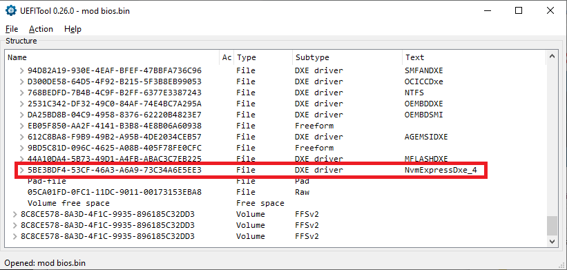
The undermost listed DXE Driver of your specific MB BIOS is named MFLASHDXE. Look here:
Problem: There is a “Pad-file” detected by the UEFITool just beyond the MFLASHDXE module and the UEFITool cannot really handle such situation (wrong insertion by MSI).
My advice: Take the AMI Aptio MMTool v4.50 instead. This tool will not touch the Pad-file (contrary to the UEFITool. The related guide can be found >here< within the chapter “a) Guide for the usage of AMI’s MMTool 4.50.0023”.
Please attach the DXE Driver you want to get inserted and I will show you how the modded BIOS should look after having opened it.
@Fernando ,
do you think this bin file could be OK?
thx and good evening,
cyanno
mod bios.rar (2.4 MB)
@cyanno :
Yes, that looks fine. You can flash it.
Usually the flashing procedure doesn’t make problems, if you rename your modded BIOS to the exact stock BIOS name (including the extension).
Good luck!
Dieter
thx, will report tomorrow! But nevertheless just one small question: could you see the NMVE driver (I was not able to do so)?
Leo
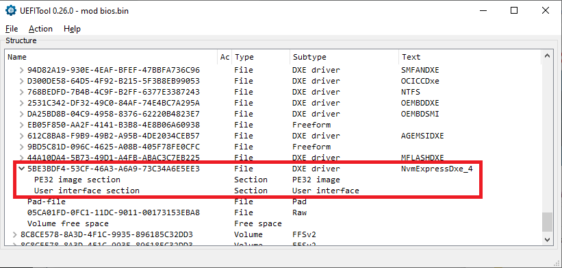
Yes, here you can see the NVMe BIOS module (left Pic not expanded, right Pic expanded):
[[File:NVMe module inserted (not expanded).png|none|auto]][[File:NVMe module inserted (expanded).png|none|auto]]
@Fernando ,
until now I made all bios dumpings and mods on a second mainboard, the one I bricked by unsolderng a wrong chip. Now that I finally had a working mod BIOS I tried to dump it on my workingt PC, the one with an identical A55M-P33 board. Result unfortunately zero, the BIOS chip was not recognized. For me not understandable, same configuration of the wiring, CH341A and mini PC, just switching the whole from one JSPI1 to the other. I tried about 5 times and finally run out of patience. Now I will wait until a spare UP0104 is arriving and soldered on the first mainboard, hoping that it is still working…
Thanks again for all your help
Cyanno
@Cyanno:
How resp. with which tool did you try to flash the modded BIOS? Which name did you give the modded BIOS?
@Fernando ,
I have 2 mainboards, one as it is and the other in a PC, full connected and running with Win10.
I only flashed the bios in the first (bricked) mainboard using the CH341A programmer with the file I send yesterday. I did´t renamed this file, just took it as it was "bios mod.bin" . After flashing I checked the bios chip by dumping it again, just to see if the driver NvmExpress_Dxe4 would be present, and yes, it was there!
The second board, the one that is working in my PC, where I intend to work with a NVME-Card and whose BIOS chip I want to mod, is my problem. If I connect the JSPI1 with the CH341A, the bios chip is not responding (with the bricked mainboard no problem!). I made no attempt at all for flashing because I´m afraid that after such a try the bios is not responding anymore.
@cyanno :
Since I never had an MSI mainboard, I have no experience with the procedure how to flash a modded MSI AMI UEFI BIOS.
It is very strange for me, that MSI delivers their BIOS as *.exe file, which just can be executed, but not extracted.
My tip: Ask our BIOS Guru Lost_N_BIOS for help. He knows much more about MSI BIOSes and how to get them properly flashed than me.
@cyanno - Sorry for late reply here!! Flash mod BIOS using stock BIOS Name.extension, not the EXE name.extension as Fernando mentioned above
Sounds like maybe your BIOS is not soldered back in correctly if you cannot see it from JSPI1, desolder it again and then solder back, maybe you didn’t get it perfectly soldered in last time you put it back
EXE BIOS can be extracted, sometimes only by running the exe on USB on the actual model in question though 
Since you have programmer, you can always use BIOS 1.7 instead of 2.0, this version BIOS is not in EXE wrapper
For BIOS 2.0 EXE - That BIOS is tricky, unsure how you should extract, there is two 4MB BIOS images in there, probably due to how that is a 1.0 to 2.0 BIOS type update
First BIOS image starts at 0x2BC3C9h and is 400000h long, ending at 0x6BC3C8h. BIOS version in this one is 0ABWM025 (V2.0) - This I believe would be the final loaded BIOS after the 1.0 to 2.0 update
Second BIOS Image starts at 0x6BC3C9h and is 400000h long / goes till end of file. BIOS version in this one is 0ABWM015 (V1.8B10). This one most like version 17, so probably flashed in first during the standard BIOS 1.0 to 2.0 update processs
For either, select range as noted above, cut that and past to new file then save and you have your 4MB BIOS images, you can then rename to E7786AMS.20 or 200 (unsure), but since you have programmer that doesn’t matter, name it .bin 
Some boards JSPI1 cannot program BIOS through, but only boot BIOS from (ie BIOS on cable, or BIOS on PCB), then remove and flash main BIOS on the board.
Since your boards are same model, it should be same with both, but maybe not if they are not same exact version #
JSPI1 port is tricky sometimes, it’s really made to be used with a BIOS on PCB/cable etc to boot directly from them remove and flash main BIOS, but you can program through it sometimes.
Hopefully you have SOI8 test clip with cable too, in case you cannot program through JSP1. Here is some JSPI1 discussions for your reference
Flashing BIOS chip (MX25L3205D) with CH341A progammer - can’t detect chip
[Guide] Recover from failed BIOS flash using Raspberry PI (11)
Xeon E3-1240 v5 working with MSI Z170-A PC MATE but with bios reset on boot (3)
@Lost_N_BIOS ,
many thanks for this answer. Again a lot of information, but for the moment I have to wait for a small 50 Ct UP0104 chip coming from China.
Perhaps you remember, I bricked my original Mainboard by desoldering the UP0104, thinking this was the BIOS Chip. I bought a second identical (???) mainboard and this PC is running without any problem.
On the bricked mainboard I was now free to do what I wanted. It is on this mainboard that I could dump the bios file (bin-file) with a JSPI1 <-> CH341A connection bought also from China, mod it with the help of Fernando and replace it again using the JSPI1 <-> CH341A connection. This was working, I could dump the modded file again, check it (at least Fernando did) and replace it. But as the mainboard is bricked (hopefully it is the UP0104) I have to wait a few weeks before replacing the UP0104 and trying this mainboard in the PC.
On my "active" mainboard I only tried to dump the BIOS file with the JSPI1 <-> CH341 connection. And this wasn´t working. Your assumption that some boards cannot program via JSPI1 therefore could be correct. But for the moment I keep my fingers far away from this working mainboard!
I will report again the moment the bricked mainboard is working and will tell if the modded BIOS file is working.
Thx again,
Cyanno
@cyanno - You’re welcome. What is UP0104? Ohh, no, sorry, I didn’t remember what happened originally (I help so many users, hard to keep track sometimes )
So, hopefully you have dumped contents that are good, that you can put back on the UP0104? Wait, why couldn’t you solder original UP0104 back into place, or did you erase it or something?
Yes, I’ve seen video direct from MSI about how it can be used, and in the past, some older boards, it’s shown to be used only as a “Boot from” type port, where you put a BIOS on cable or PCB connected to that and boot to it, then remove and program main BIOS as normal from USB.
But, I’ve seen some others have success on some boards direct programming through it too. Personally, I’ve only ever used it as a “Boot from” with a PCB adapter I have that has Asus/MSI header on either end with BIOS chip in the middle.
Hopefully you can fix your board once the UP0104 package arrives 
@Lost_n_BIOS,
of course it is not possible to memorize eveything, just for your info:The Beginners Guide to Using a CH341A SPI Programmer/Flasher , Post #96! -> UP0104 is a converter, cannot be programmed.
But the BIOS on the bricked board is probably modded and flashed correctly. We will see!
@cyanno - Thanks, I see the post now So, why didn’t you just solder that UP0104 back into it’s original place?
@Lost_N_BIOS , just in the beginning, I tried so many time to get a connection between the UP0104 and the CH341A clip that I probably destroyed one leg of the UP0104, at least the pc was not working anymore. I just desoldered it afterwards, and now I´m waiting for the spare UP0104!
Well, it was not working before too though, correct? But yes, if you could see you destroyed a leg then nothing to do but replace, hopefully they’ll arrive soon as your solder session will go smoothly
Can I use the add absent EFI module to say add a GOP module to an Asus Z390 BIOS that doesn’t have it natively? I think one of the connectors on the backplate can use an adapter to output to a second screen if you do this.
The BIOS I mean is the Maximus XI Apex and Maximus XI Gene 1301 BIOS’s.
I had a request for that mod, I just want to make sure it’s actually feasable.