Intro and warning
Warning: Flashing this modified UEFI firmware may permanently brick your motherboard. Proceed only if you fully understand the risks! I am not responsible for any damage, bricked hardware, or other issues caused by this firmware. Flash at your own risk.
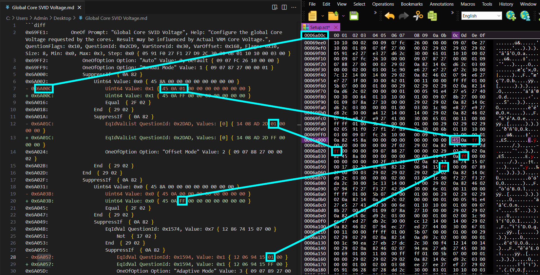
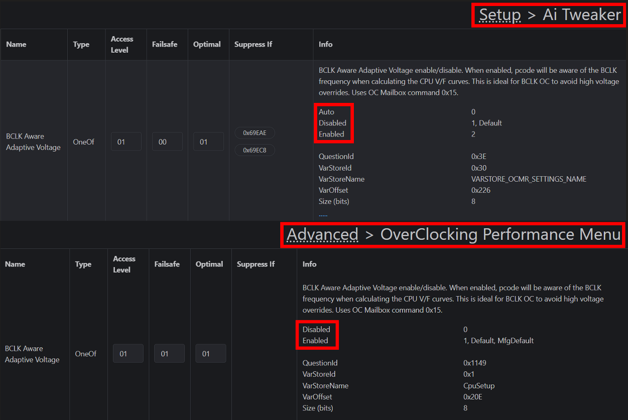
This is a modified UEFI firmware for the ASUS ROG STRIX B760-I mini-ITX motherboard (firmware version 1805 with Intel’s 0x12B microcode) to enable undervolting and overclocking. This modification unlocks the ability to set the Global Core SVID Voltage to adaptive or offset mode.
All settings remain at their defaults, so you’ll need to manually toggle the necessary locks before making any changes. The main reason I modified this firmware was to unhide CFG Lock, which improves power management in macOS with OpenCore for Hackintosh setups.
Important Notes
- Use only on ASUS ROG STRIX B760-I running firmware version 1805 or lower.
- This motherboard was not designed for overclocking, and some of these hidden features may have been disabled by ASUS for good reason. While this firmware unlocks these features, their functionality and stability are not guaranteed. So far I haven’t noticed any issues though.
- Advanced features present on higher-end ASUS Z-series motherboards are still missing from this modification. Features such as Extreme Tweaker, AI Features, and Silicon Prediction (SP Score) were not present at all in the firmware for the B760-I motherboard, so of course they can’t be unhidden.
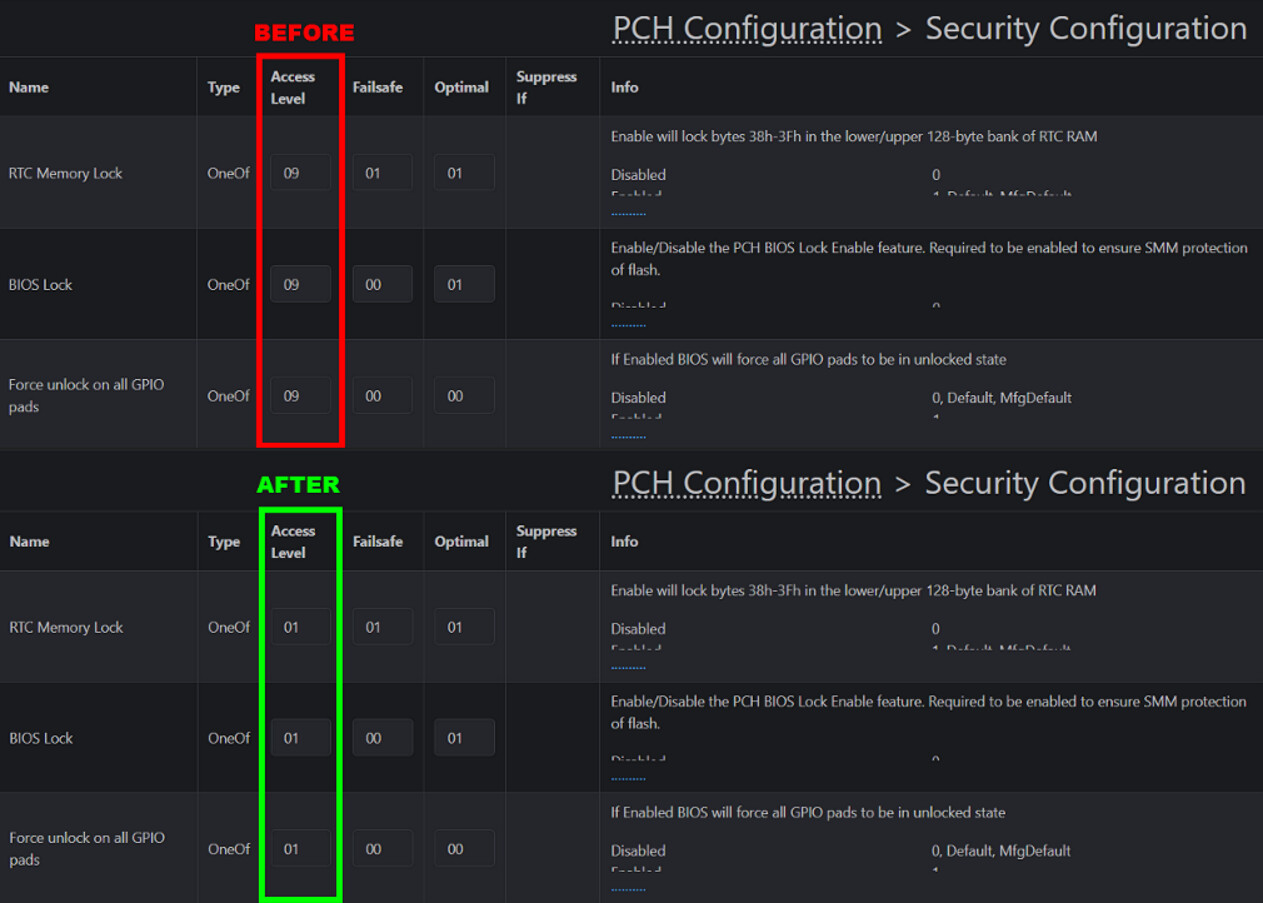
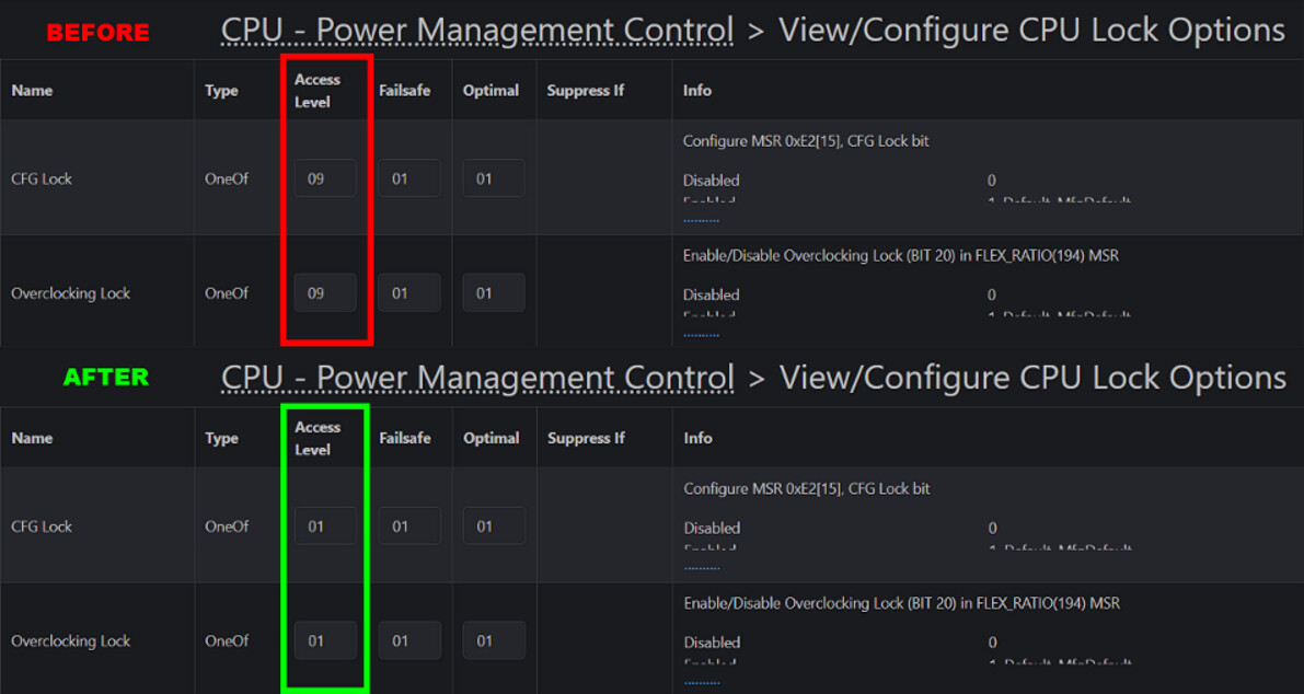
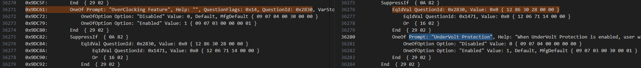
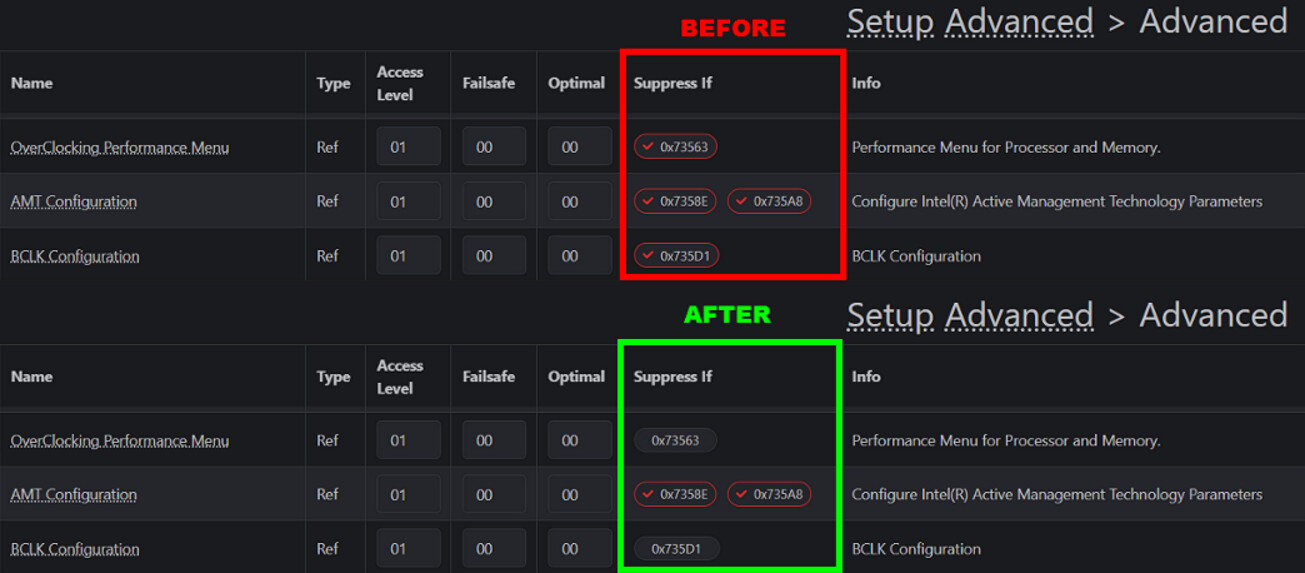
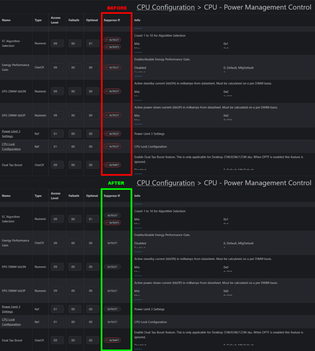
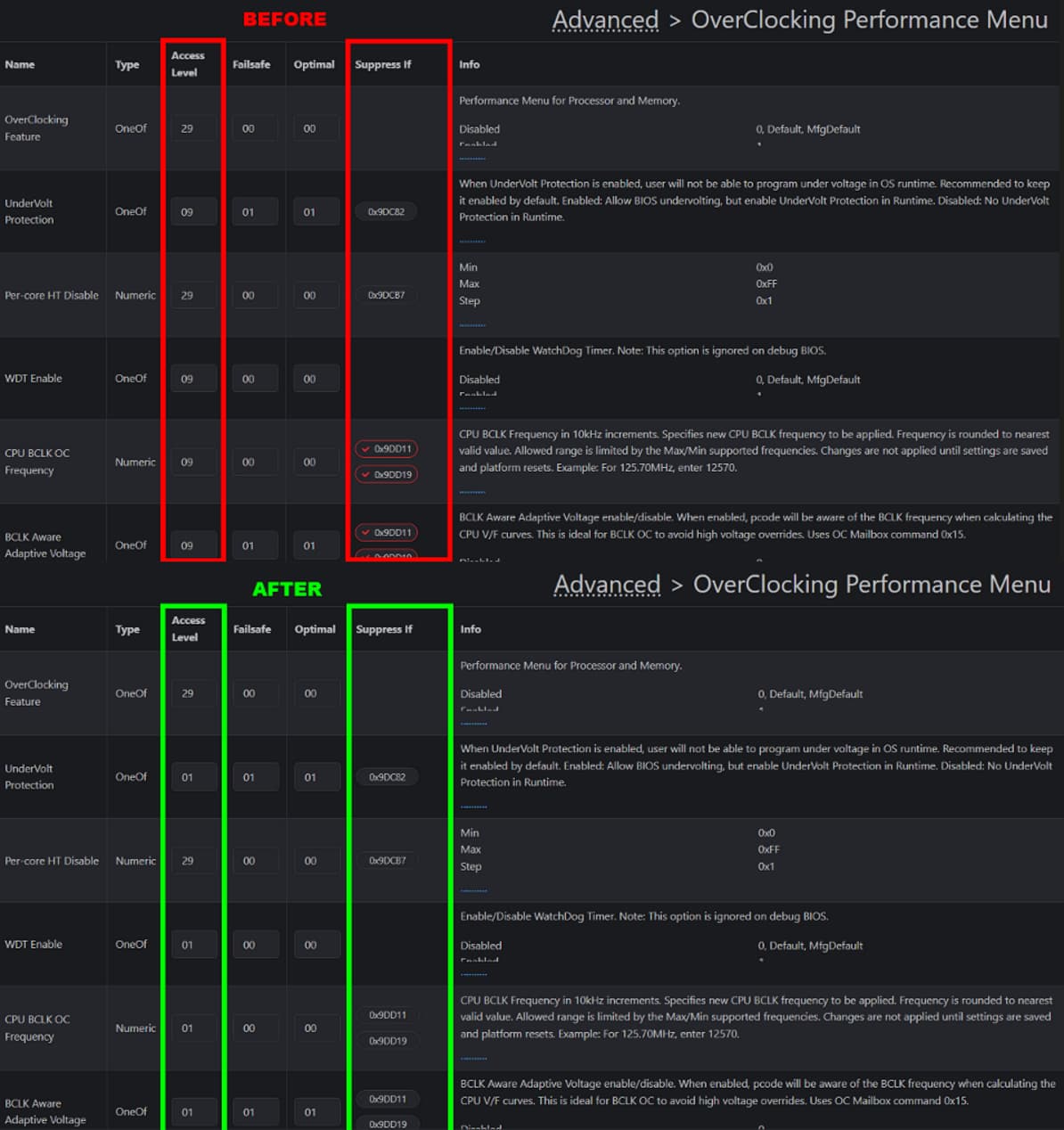
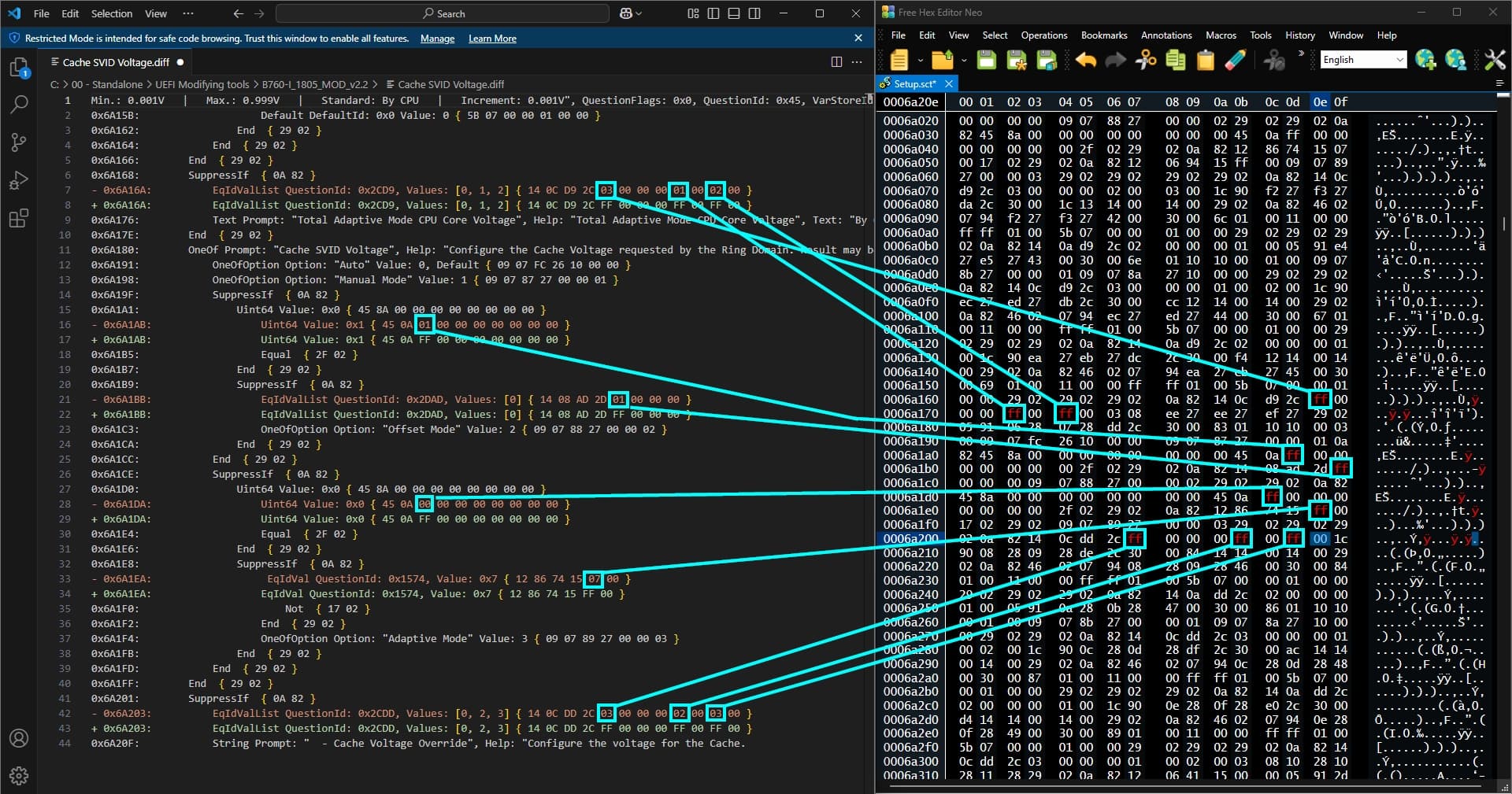
- Using UEFI-Editor, I modified the access level of hidden features from 9 to 1, which unlocked several menus and additional options dependent on the ones listed below. These changes also revealed many advanced settings, including options that may not have been designed for end-user access.
Unhidden Features
Unlocked Drop-Down Menu Options
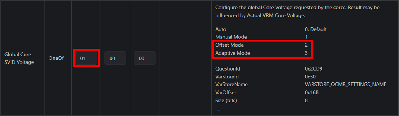
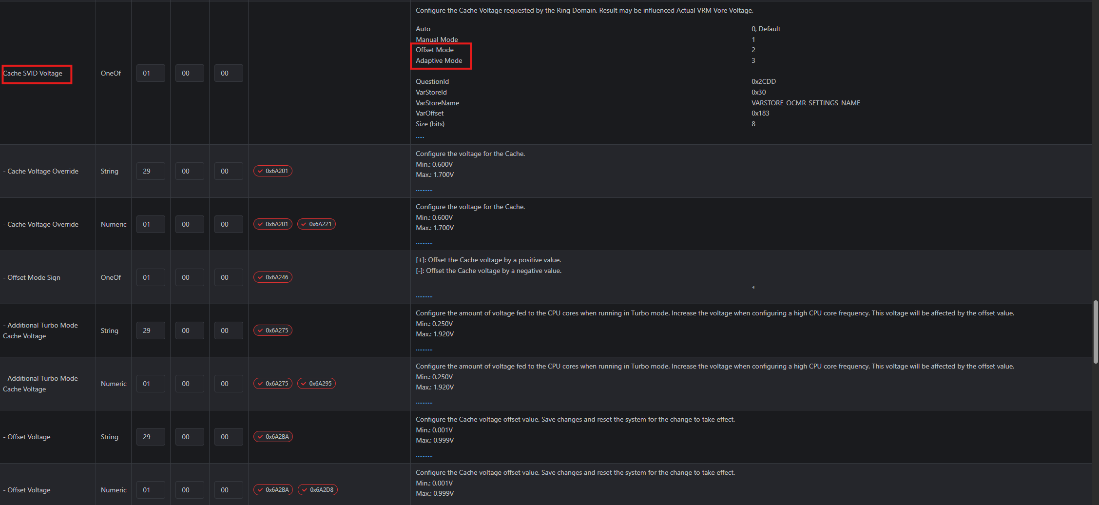
Global Core SVID Voltage
- New Options: Adaptive and Offset

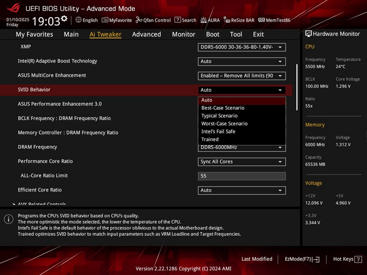
SVID Behavior
- New Option: Trained
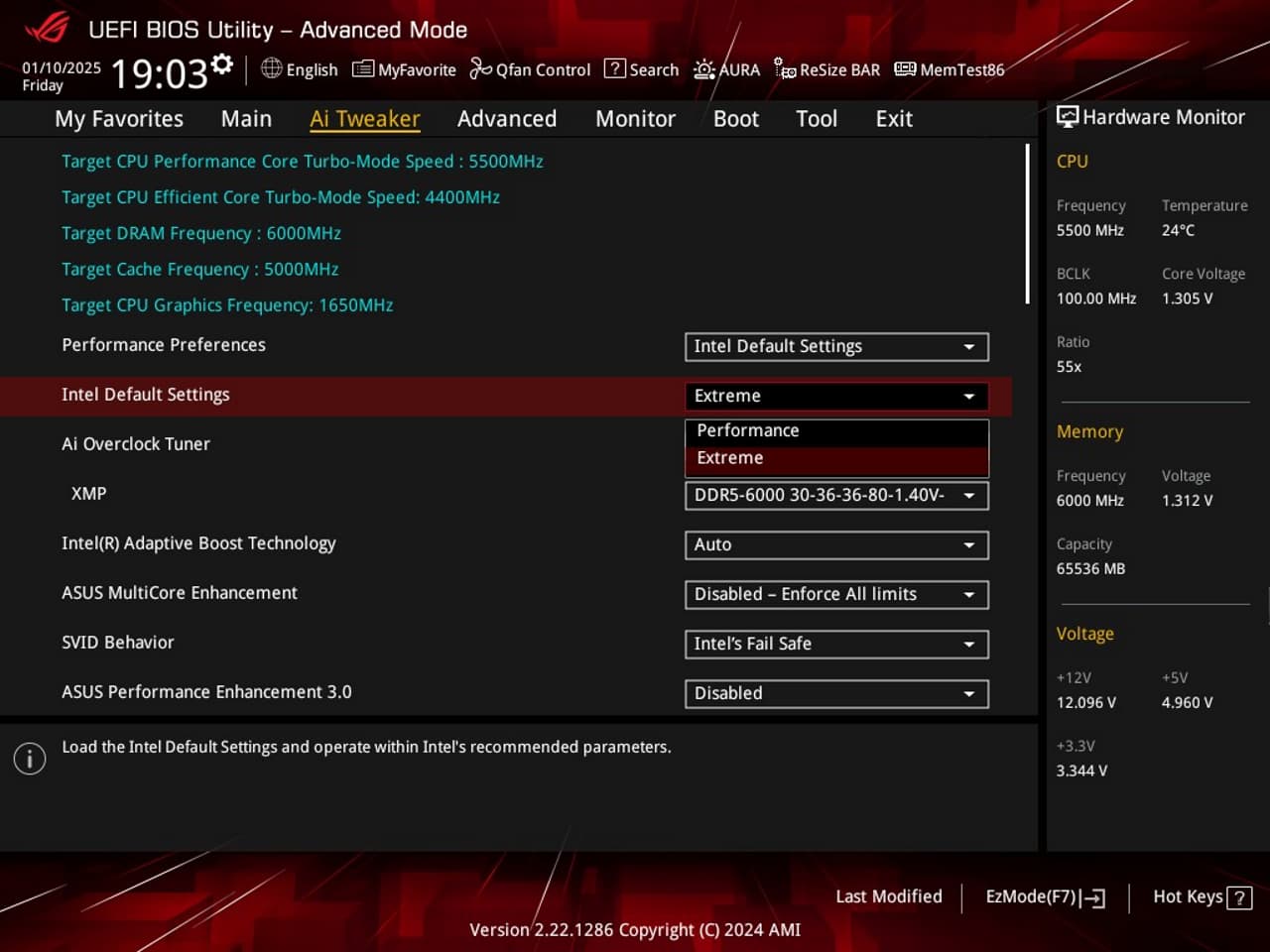
Intel Default Setting
- New Option: Extreme
New Menus
CPU Lock Configuration
Advanced → CPU Configuration → Power Management Control → View/Configure CPU Lock Options
- Includes options to enable or disable CFG Lock and Overclocking Lock

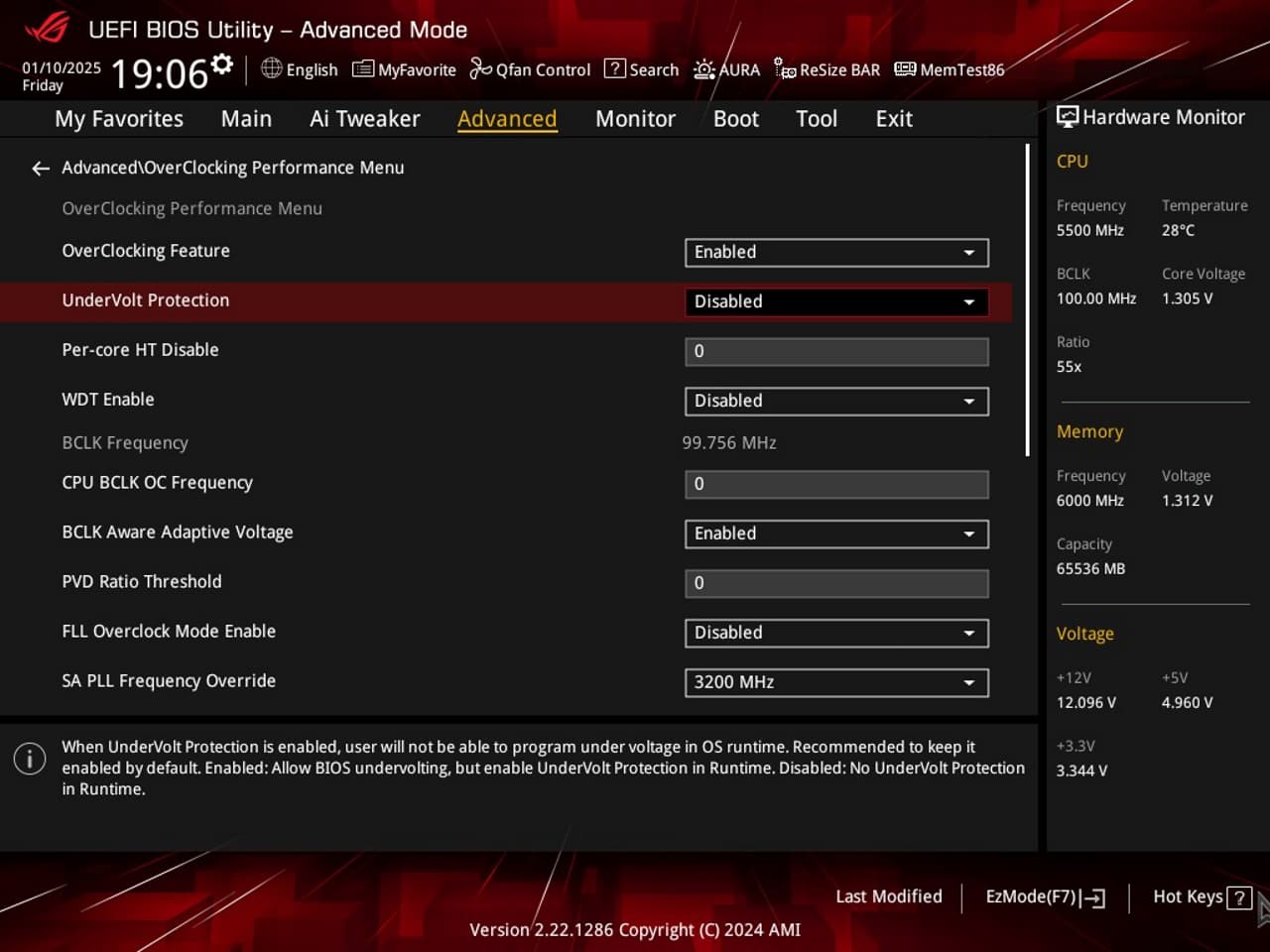
OverClocking Feature
Advanced → OverClocking Performance Menu
- Adds extensive overclocking capabilities, including frequency and voltage tweaking.
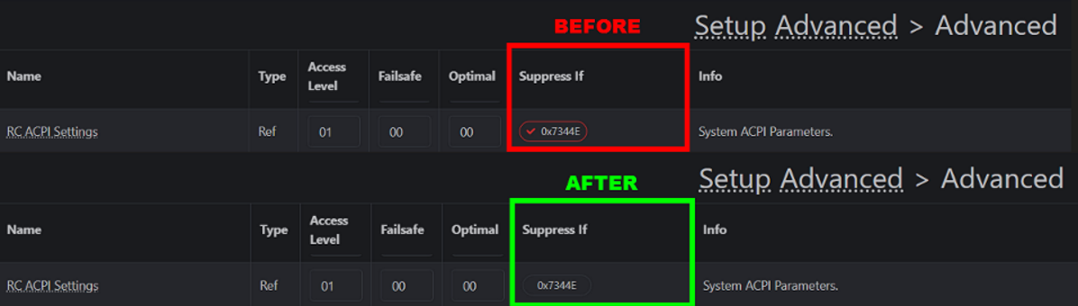
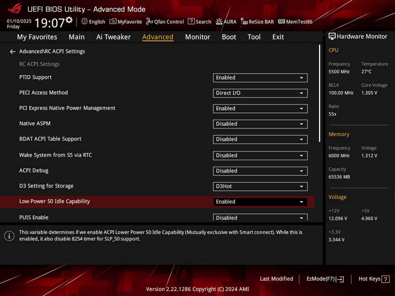
RC ACPI Settings
Advanced → RC ACPI Settings
- Unlocks power state-related options, including “Low Power S0 Idle Capability.”
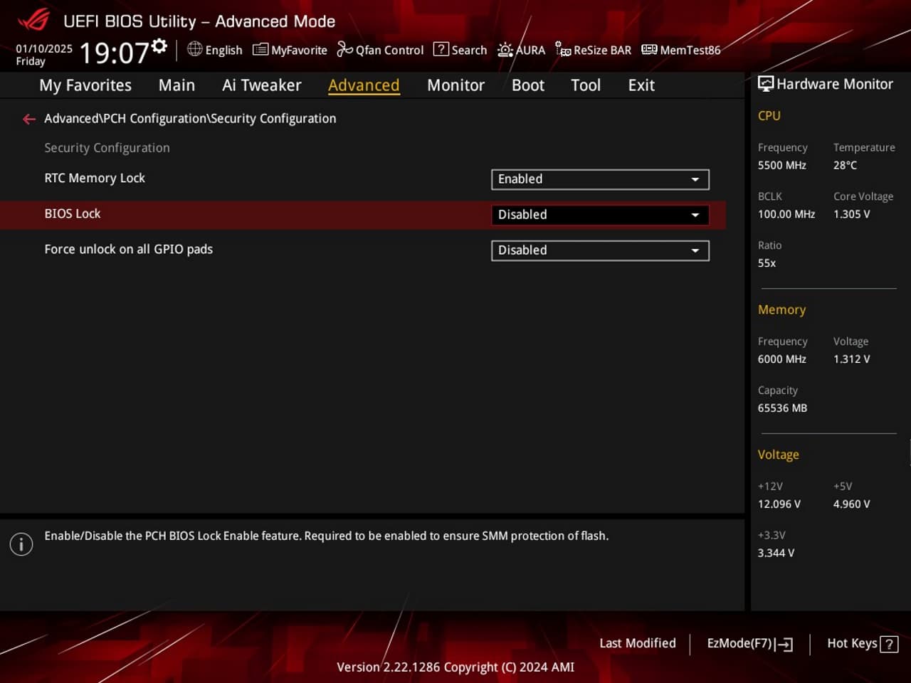
Security Configuration
Advanced → PCH Configuration → Security Configuration
- Unlocks additional security-related settings tied to platform controllers.
Instructions
Requirements
- Windows 10 or Windows 11
- Intel Management Engine: Drivers, Firmware and Tools for ME 16+
- AMISCE/WINSCE (SCEHUB)
- Visual Studio Code (Optional)
Introduction
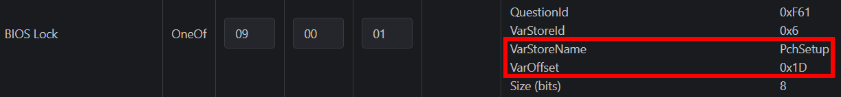
To flash the firmware, we first need to unlock the BIOS lock. Since this is hidden in the stock firmware, we cannot simply toggle the setting through the BIOS interface. Instead, we’ll need to modify the values via NVRAM. There are several guides on WinRaid that use modified grub, setup_var, and RU.EFI tools to achieve this. However, all three of these applications encountered errors due to write protection.
The only tool that worked for me was AMI SCE / WinSCE. The others produced the following errors:
RU.EFI 5.34.0426-BETA:
Error: Write variable failed (0x0000001A)
Setup_var.efi (0.3.0):
Error: Failed to write variable
Error: Failed to set content of variable CpuSetup (SECURITY_VIOLATION)
grub-mod-setup_var.efi (2.06):
Error: Unable to set variable using EFI (Error: 0x000000000000008a)
Preparation
-
Boot into BIOS by pressing F2 at boot, press F5 to restore factory defaults, then press F10 to save and reset.
-
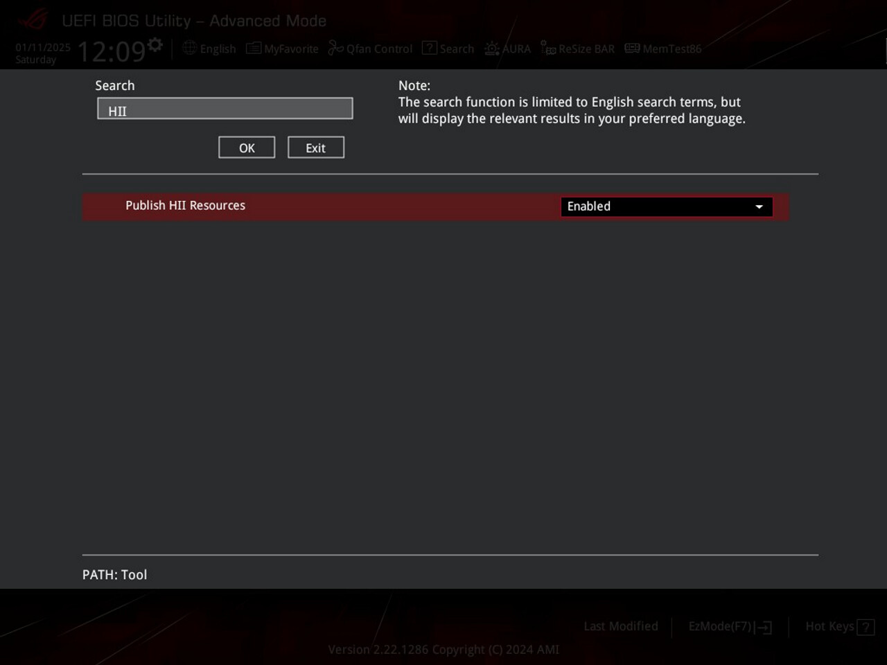
Boot into BIOS again with F2. Set the following two options (Use F9 to Search):
- Setup → Tool → Publish HII Resources = Enabled
- Setup → Advanced → UEFI Variables Protection → Password protection of Runtime Variables = Disabled
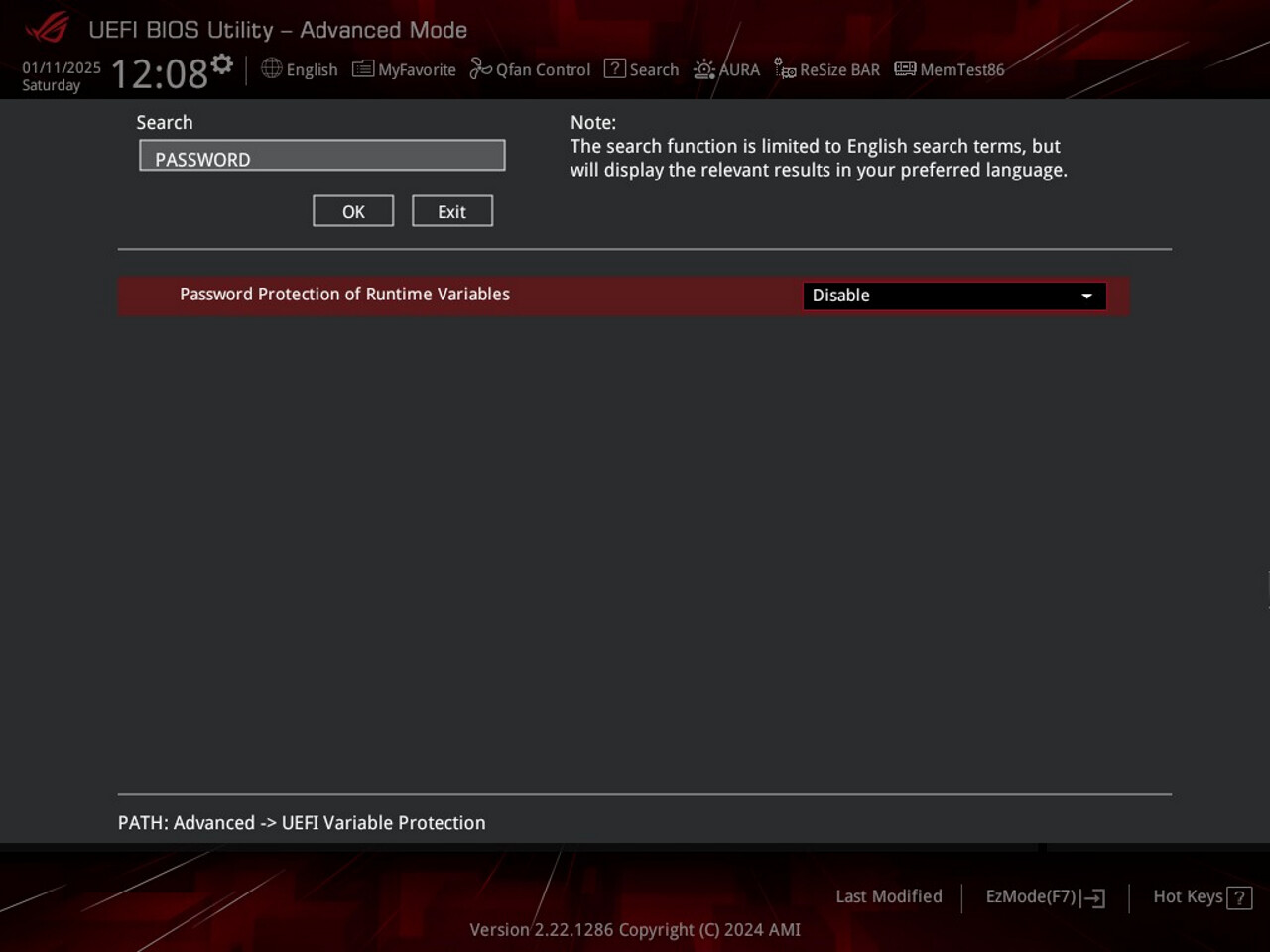
- Press F10 to save and boot into Windows 10 or 11.
Downloading AMI SCE / SCE WIN
- Navigate to AMISCE/WINSCE (SCEHUB) and download the latest release. Launch DL_SCEWIN.exe, which will open a command prompt window. SCEWIN should begin downloading automatically. Be aware that it might take some time for any activity to appear; in my case, the prompt remained black for an extended period before progressing.
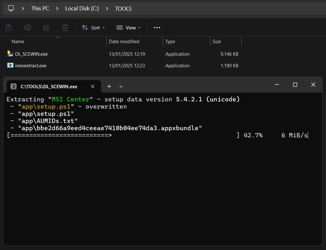
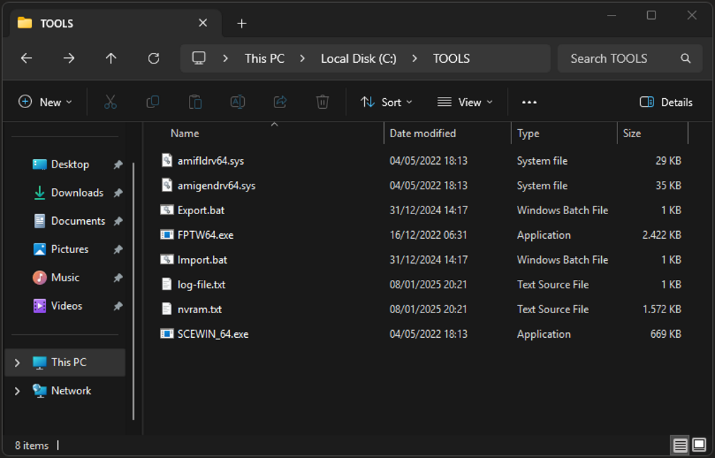
- Optional: Once the process is complete, copy the contents from
.\SCEWIN\5.05.01.0002toC:\TOOLS.
Download Flash Programming Tool (FPTW64)
-
Download FPTW64 from Intel Management Engine: Drivers, Firmware and Tools for ME 16+ and extract the archive.
-
Optional: Copy the
FPTW64.exefromCSME System Tools v16.1 r0\Flash Programming Tool\WIN64toC:\Tools.
Create a backup
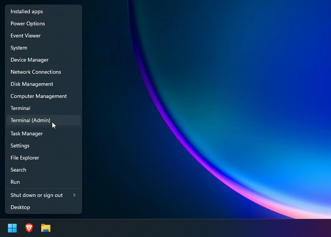
Right click start, open PowerShell as Administrator and navigate to the folder where FPTW64.exe is located.
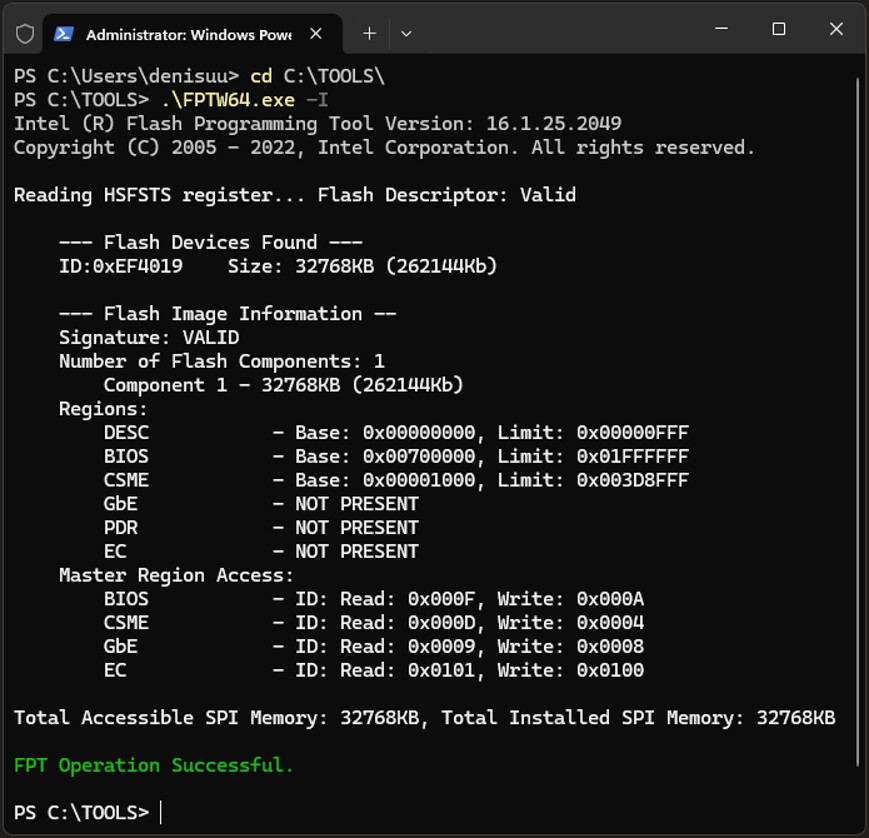
Run the following command to check if FPTW64 is working: .\FPTW64.exe -I
If this is was successful you can now create a backup by dumping the BIOS, I recommend doing this at least two to four times and comparing the resulting file hashes to verify the integrity of the dump.
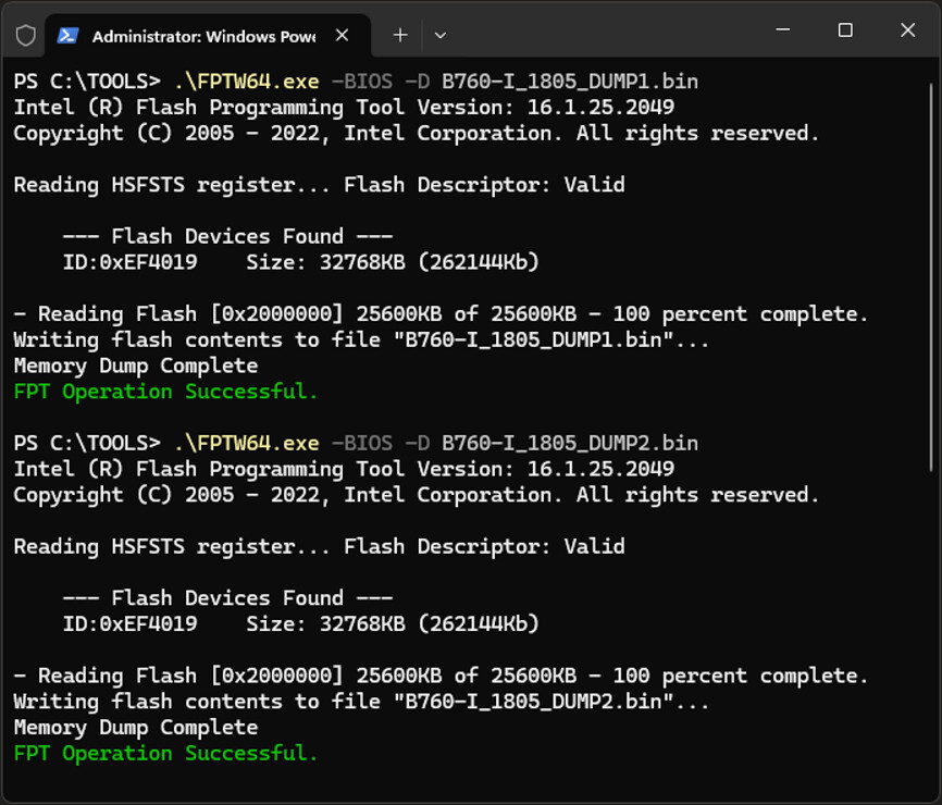
Run the following command to create the first backup:
.\FPTW64.exe -BIOS -D B760-I_1805_DUMP1.BIN
After the first dump is complete, repeat the process with a new file name for the second dump:
.\FPTW64.exe -BIOS -D B760-I_1805_DUMP2.BIN
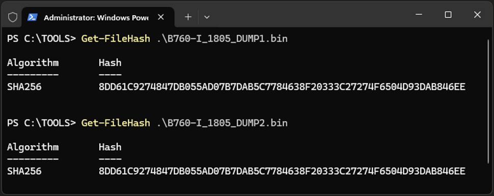
Next, compare the two hashes to ensure the files are identical and verify that both are 32,768 KB (32 MB) in size. If the files meet these conditions, store them in a secure location. This will allow you to recover the firmware using a hardware flasher if anything goes wrong.
To compare the hashes, use the following command:
Get-FileHash .\Filename.bin
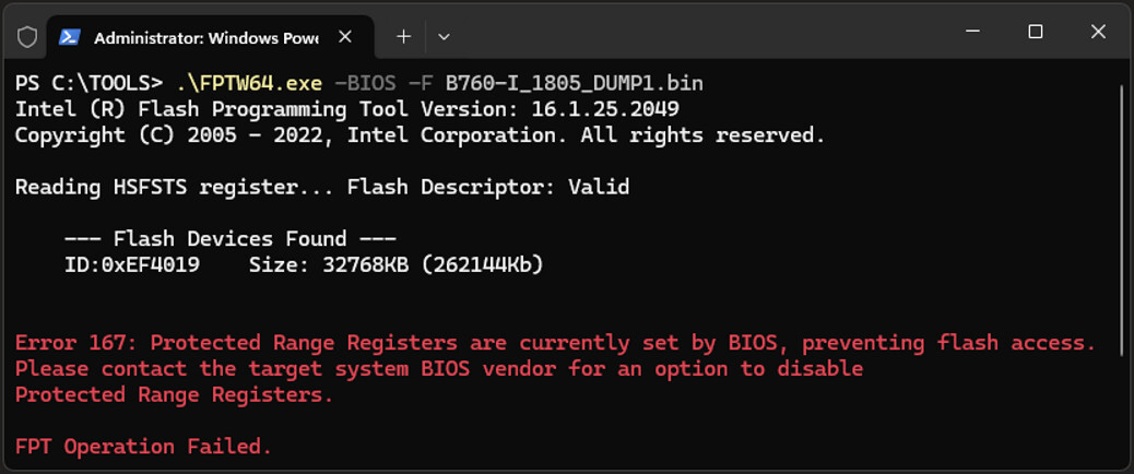
We can try to flash them back but you will see the BIOS lock prevents this. Try:
.\FPTW64.exe -BIOS -F B760-I_1805_DUMP1.BIN
Extract the NVRAM variables
Next, open PowerShell with administrative privileges and navigate to the folder where SCEWIN_x64.exe is located (in my case, it’s the same folder: C:\Tools).
Then, run the command:
.\Export.bat
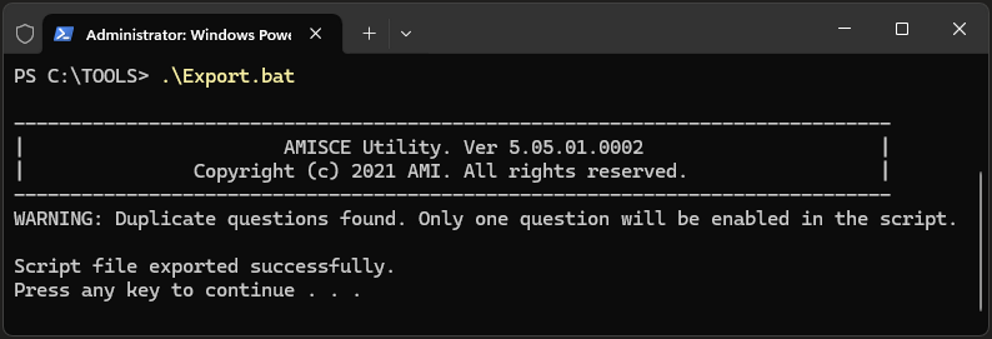
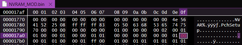
A new file named nvram.txt should appear in the folder. Open it in a text editor, then open a new, empty file.
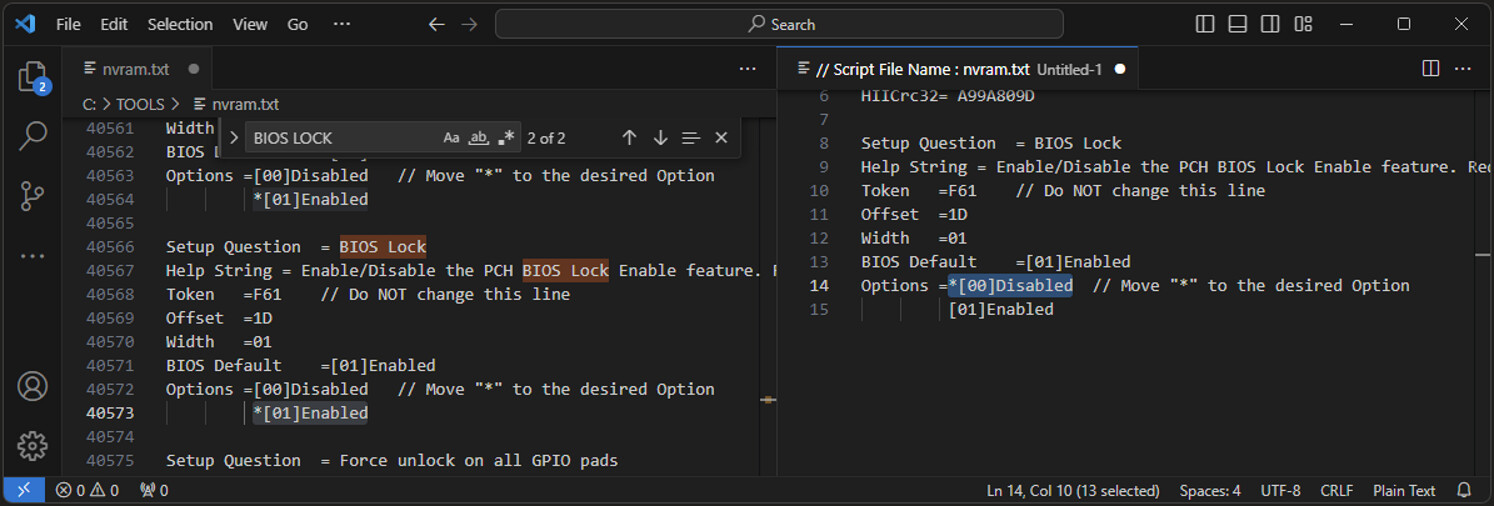
Copy the first few lines from nvram.txt into the new file.
Next, use CTRL + F to search for BIOS lock. Once located, copy the block of code containing the BIOS lock to the new file and move the asterisk from [Enabled] to [Disabled]
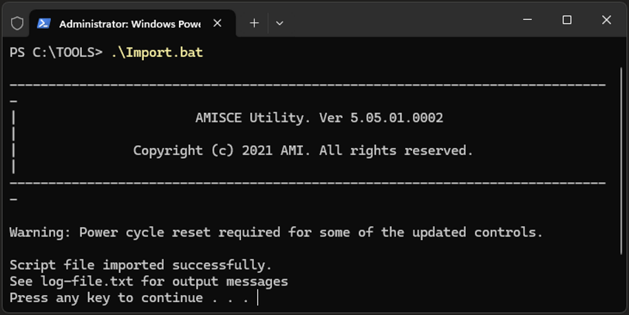
Run .\Import.bat through PowerShell.
Reboot your PC, then open PowerShell as Administrator once more.
Navigate back to the folder containing FPTWIN64, and copy the modified firmware (downloaded from the bottom of this page) into the folder.
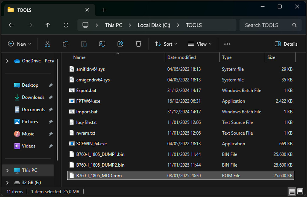
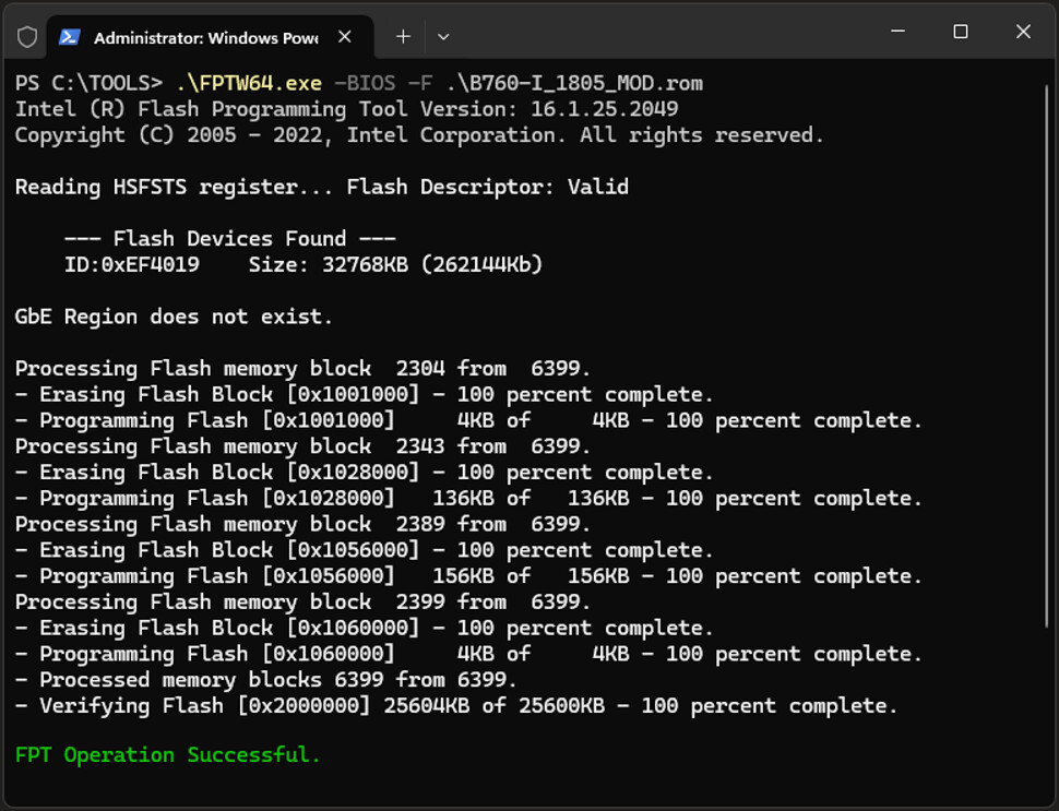
Flash the modified firmware using the following command (it should succeed now):
.\FPTW64.exe -BIOS -F B760-I_1805_MOD.BIN
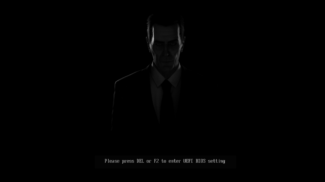
Reboot your PC again, and you should see a screen prompting you to press F1 to enter BIOS and F5 to reset to factory defaults.
Don’t worry if the first boot takes longer than usual. This is normal after flashing new firmware. Once the process is complete, the GMAN should appear, and the hidden features will be accessible when you enter the UEFI BIOS.
Recovery: Flashing the SPI Chip
If flashing went wrong, your device is unresponsive, or you’re working with a motherboard where the BIOS Lock can’t be disabled through software, you’ll need a hardware flasher like the CH341A. These programmers are very inexpensive, but you’ll need to do the 3.3v voltage mod to avoid damaging the board.
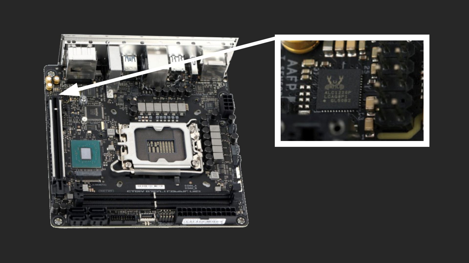
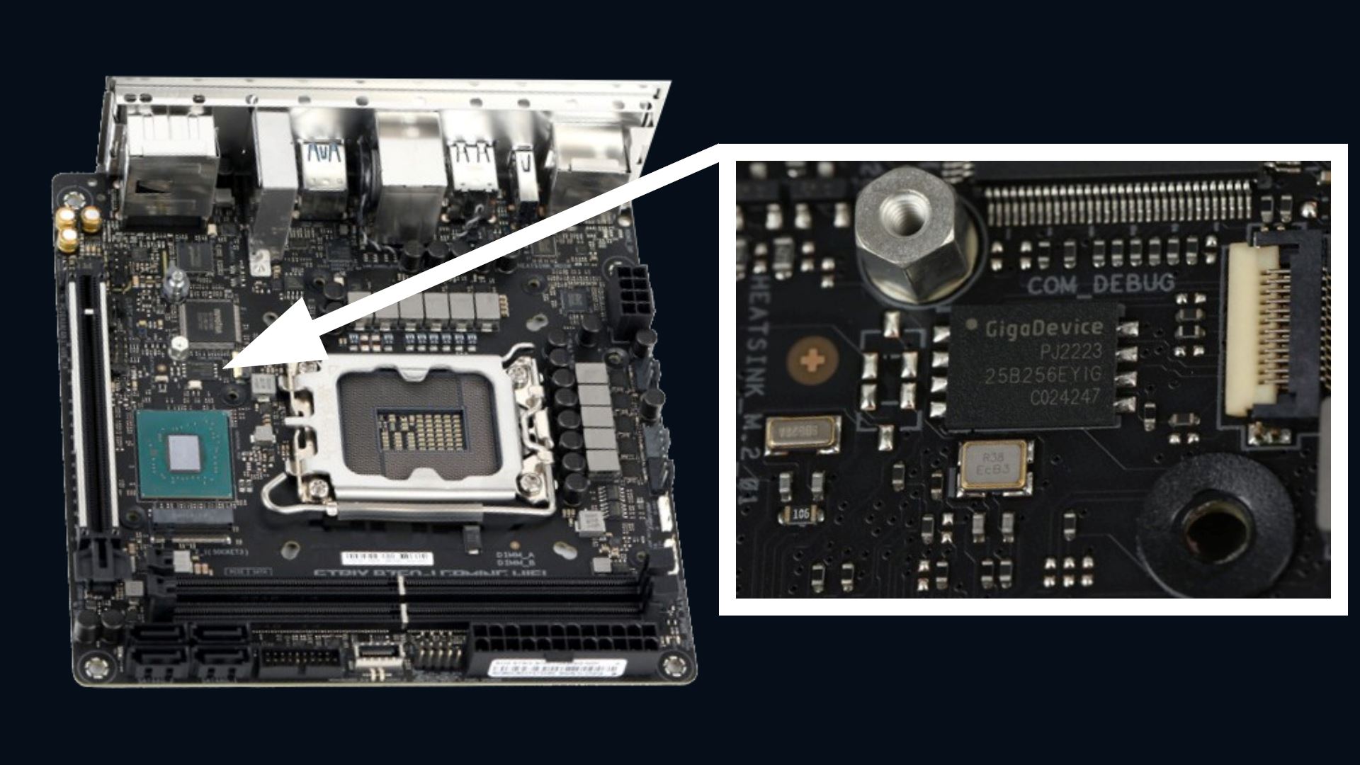
On my board, the chip was a GigaDevice 25B256EYIG, but I’ve also seen images online of this specific board using a Winbond chip. While the specific chip on your board may vary, there should be a 32MB WSON-8 chip there. Unlike traditional chips, WSON-8 chips don’t have exposed pins, their solder pads are underneath. Fortunately, on this board, the pads extend slightly beyond the chip’s edge, making it possible to use an 8x6 Pogo Pin adapter for a non-invasive connection.
The chip is located between the screw for securing the NVMe drive and the Intel B760 chipset.
Hardware Setup
I bought all of these for very cheap on AliExpress.
- CH341A programmer: ~€3
- WSON 8x6 Pogo-pin adapter: ~€12
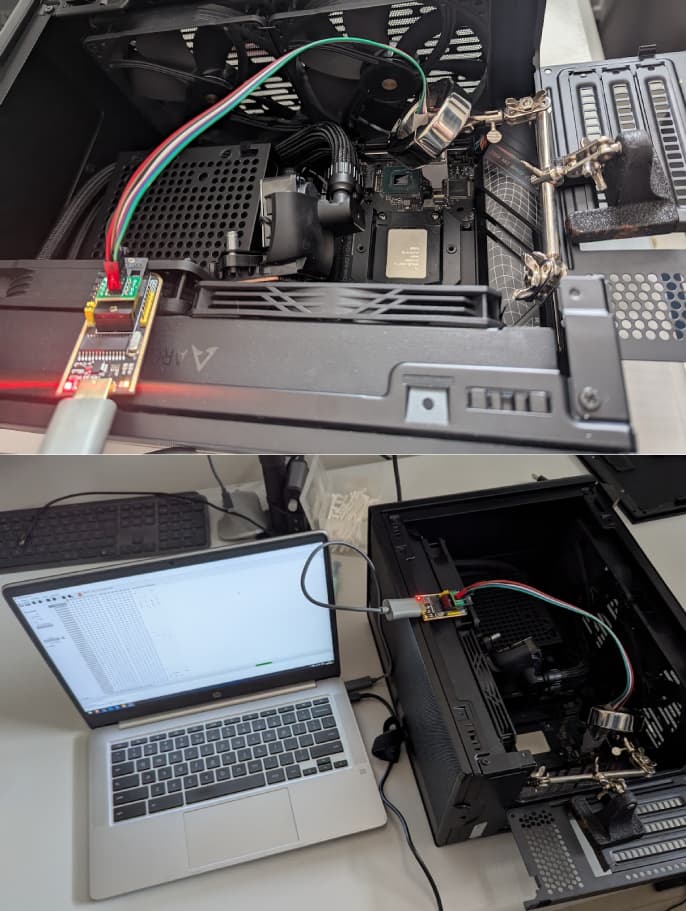
- Soldering arm: ~€6
Initially, I held the pogo-pin adapter manually while flashing the chip. However, since the process takes 15 minutes in AsProgrammer and 20 minutes in NeoProgrammer, my hand got tired, and slight movements caused errors. To stabilize it, I used a €6 soldering arm and placed a weight on top to keep it steady.
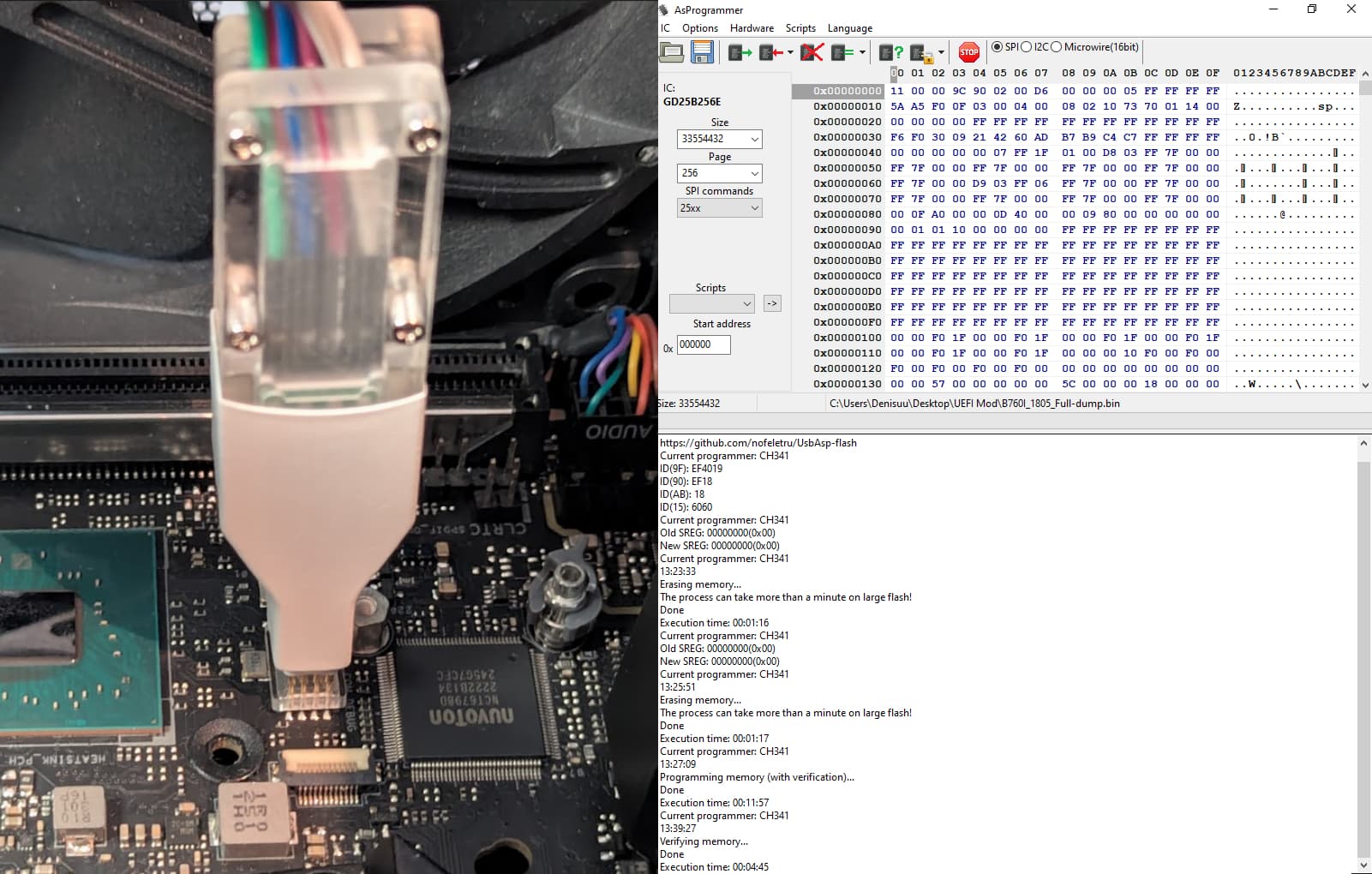
Using AsProgrammer
For this chip, I recommend using AsProgrammer 2.1.2 since it already includes support for the GD25B256E and writes slightly faster than NeoProgrammer.
Here’s the flashing process:
- Click
Read IDand selectGD25B256E. - Click the arrow next to
Program IC, then choose:Unprotect → Erase → Program → Verify - After flashing, do an extra
Verify ICstep to confirm the write was successful.
Using NeoProgrammer
If AsProgrammer doesn’t work or you prefer NeoProgrammer, you can use it as well, but you’ll need to manually import the chip. Save the following content as Import.xml:
<?xml version="1.0" encoding="utf-8"?>
<chiplist>
  <SPI_NAND>
    <GIGADEVICE>
      <GD25B256E id="EF4019" page="256" size="33554432"/>
    </GIGADEVICE>
  </SPI_NAND>
</chiplist>
Download

SHA256: 0A19F92BD6480B115F67E6B74A45256D6977047F95A7AA6325793A49CCAF6AC9
MD5: E4B0788BDDB4B08138860C78DC1B97D