-
This guide will show you how to change (enable, disable, etc.) hidden BIOS settings. It will not show you how to unhide them in BIOS setup because I haven’t found a way to do that.
-
For now, I have only been able to test this on my Z690 Aorus Elite DDR4 but in theory this guide has the potential to work for other mainboards too. However,
-
Since this involves modding the BIOS, do not attempt this, if unless have sure-fire way of recovering in case the mainboard does not boot! This could be Gigabyte QFlash Plus (which I will cover in this guide) or a hardware SPI flash programmer (not covered in this guide).
-
Read the entire guide before you start doing things, because before you do anything, know that you need to be prepared to
- use a hex editor,
- open your PC case.
- Also be aware that there is an easier way described at the end of the guide, that you can use if you have AMI SCE. It does not involve modifying the BIOS at all.
Enabling hidden BIOS settings on Gigabyte Z690 mainboards
1. Preparation
1. Preparation
- I recommend, you create a work folder, to store the files and tools needed. Like “D:\Z690 BIOS mod”
- Download a BIOS update from Gigabyte and extract the BIOS file (e.g. Z690AORUSELITEDDR4.F23) into the work folder.
- get the tools needed
All of these tools are open source, except for Intel’s FPT and the hex editor (but you can use any hex editor you like of course), and you can compile them from scratch if you like. All of these tools are also available for Linux, if you prefer that (including Intel FPT).
Intel (R) Flash Programming Tool Version: 16.0.15.1735 (FPTW64.exe) from Intel CSME ADP tools (v16.0 r8)
IFRExtractor RS v1.5.1 (ifrextractor.exe)
UEFITool NE A65 (UEFITool_NE_A65_win64.zip)
UEFITool 0.28.0
A hex editor. I will use the free version of Hex Editor Neo
Now you have all the tools needed.
- Extract FPTW64.exe and ifrextractor.exe into the work folder
- Prepare a flash drive
Ensure that the flash drive’s file system is FAT32.
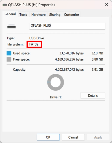
- Copy the BIOS file from the BIOS update download onto the drive (e.g. Z690AORUSELITEDDR4.F23).
Put it in the root folder. - Create a BIOS settings profile
Reboot and enter the BIOS.
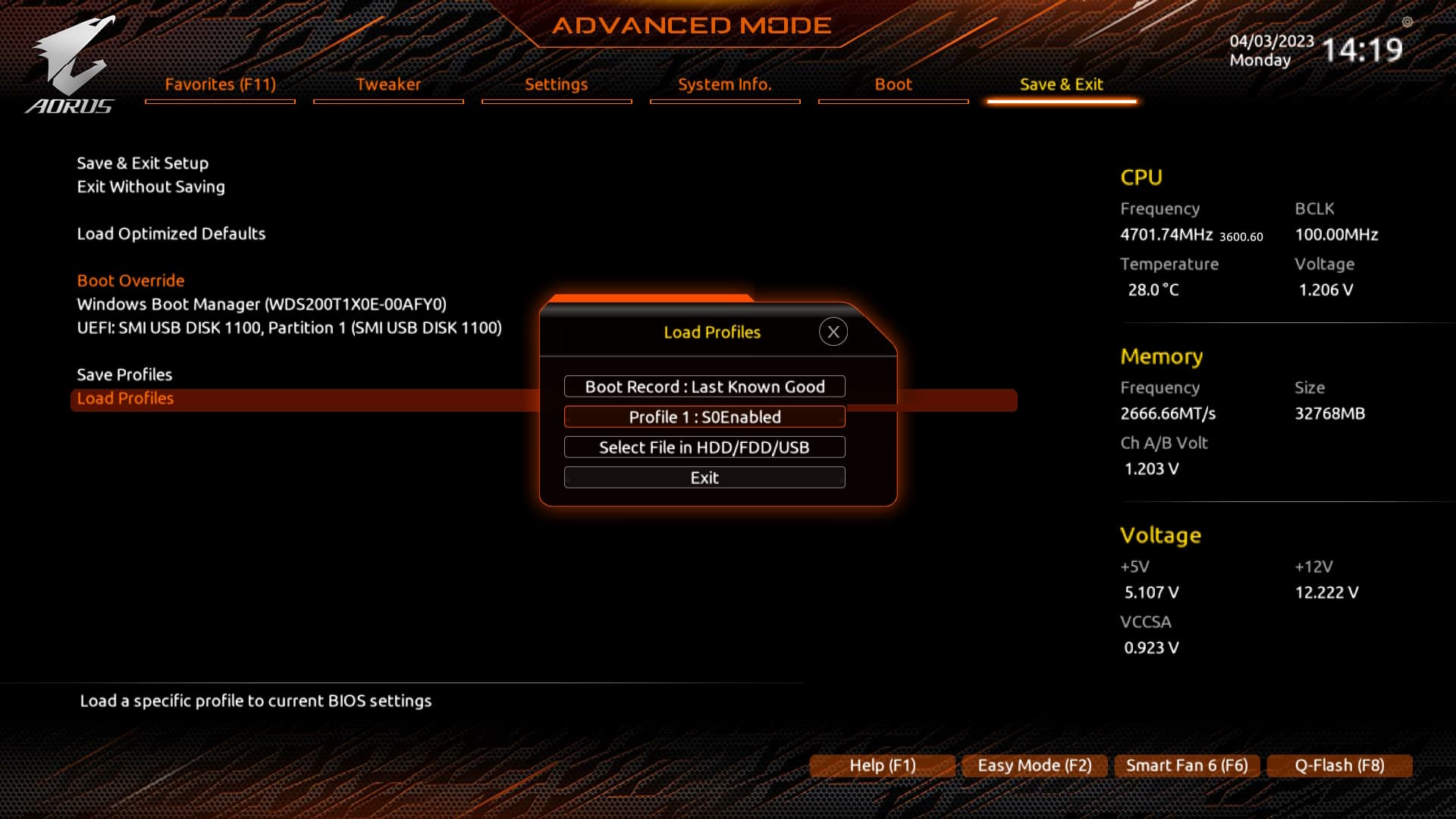
Enter Advanced Mode (F2 key) and go to “Save and Exit”
Save a new profile. The profile needs to be saved in a free slot (on the flash chip). Do not save it in a file using the “HDD/FDD/USB” option. Ensure, that the name is not too long, not too short, and not too generic!
Ensure, that you can successfully load the profile.
Remember the name and profile number. Here, I named it “S0Enabled” and it is profile number 1. - Disable SPI protections
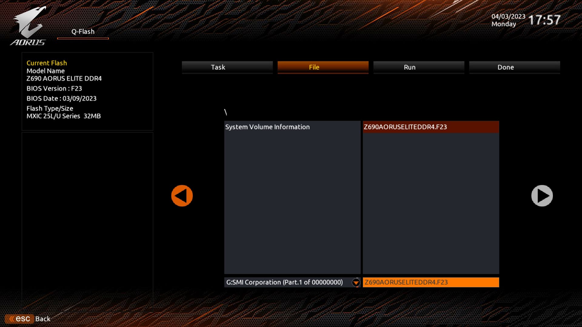
While still in BIOS, start QFlash (F8 key). Click on “Update BIOS”.
Select the file with the BIOS update on the flash drive.
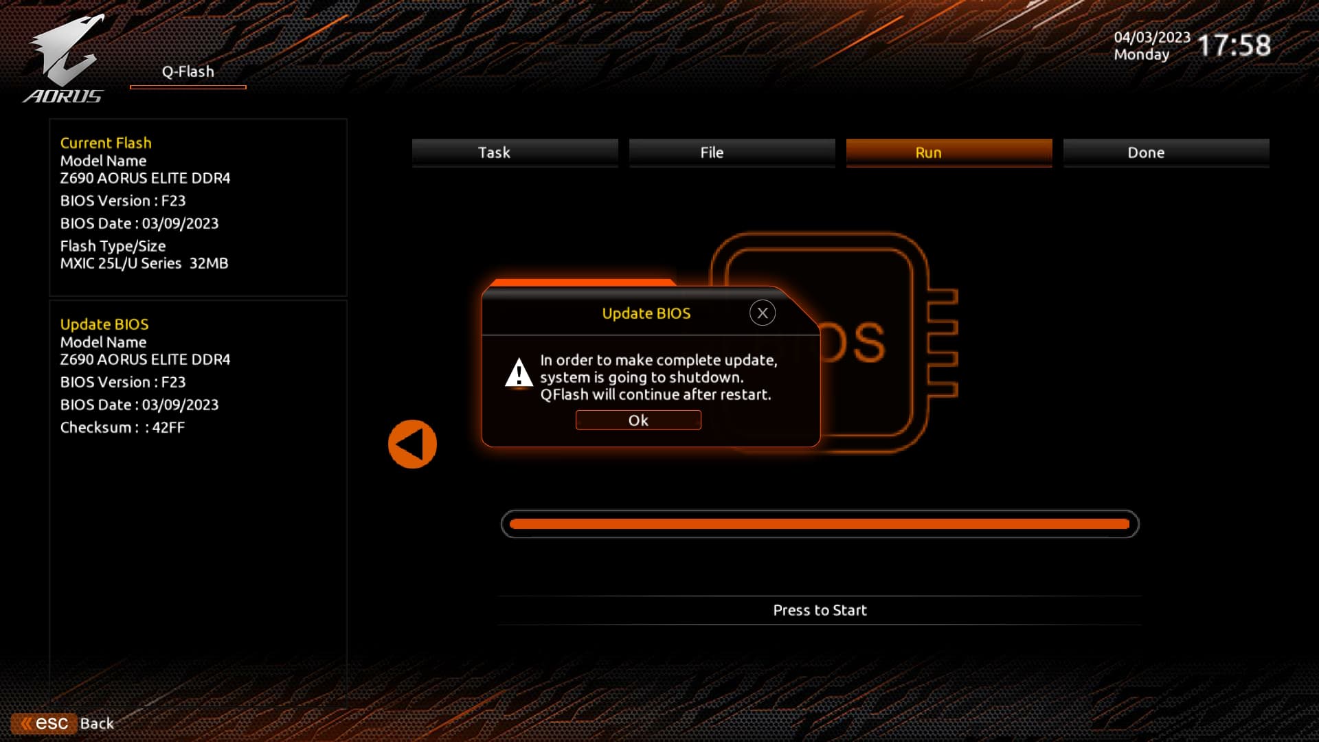
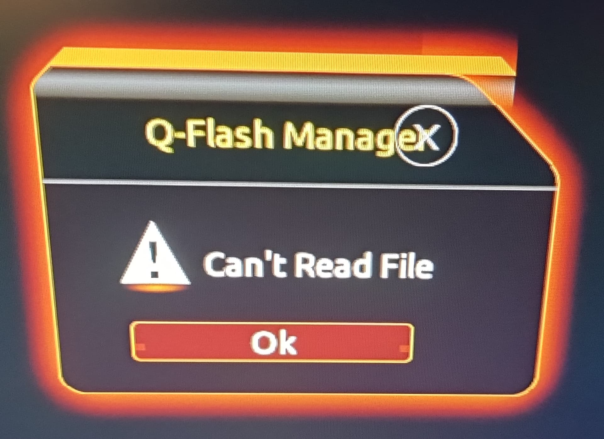
Proceed until you see the message “QFlash will continue after restart”.
Remove the flash drive. When the flash drive has been removed, click “OK”. The system will reset, QFlash will start again and you will see an error from Q-FLash Manager.
Acknowledge the error and click on “ESC Back” or press Ctrl-Alt-Del.
It should reset once again, and then boot the operating system.
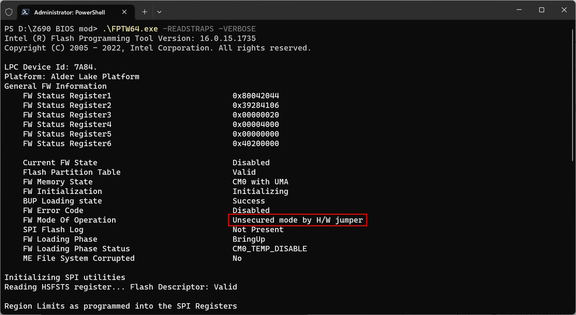
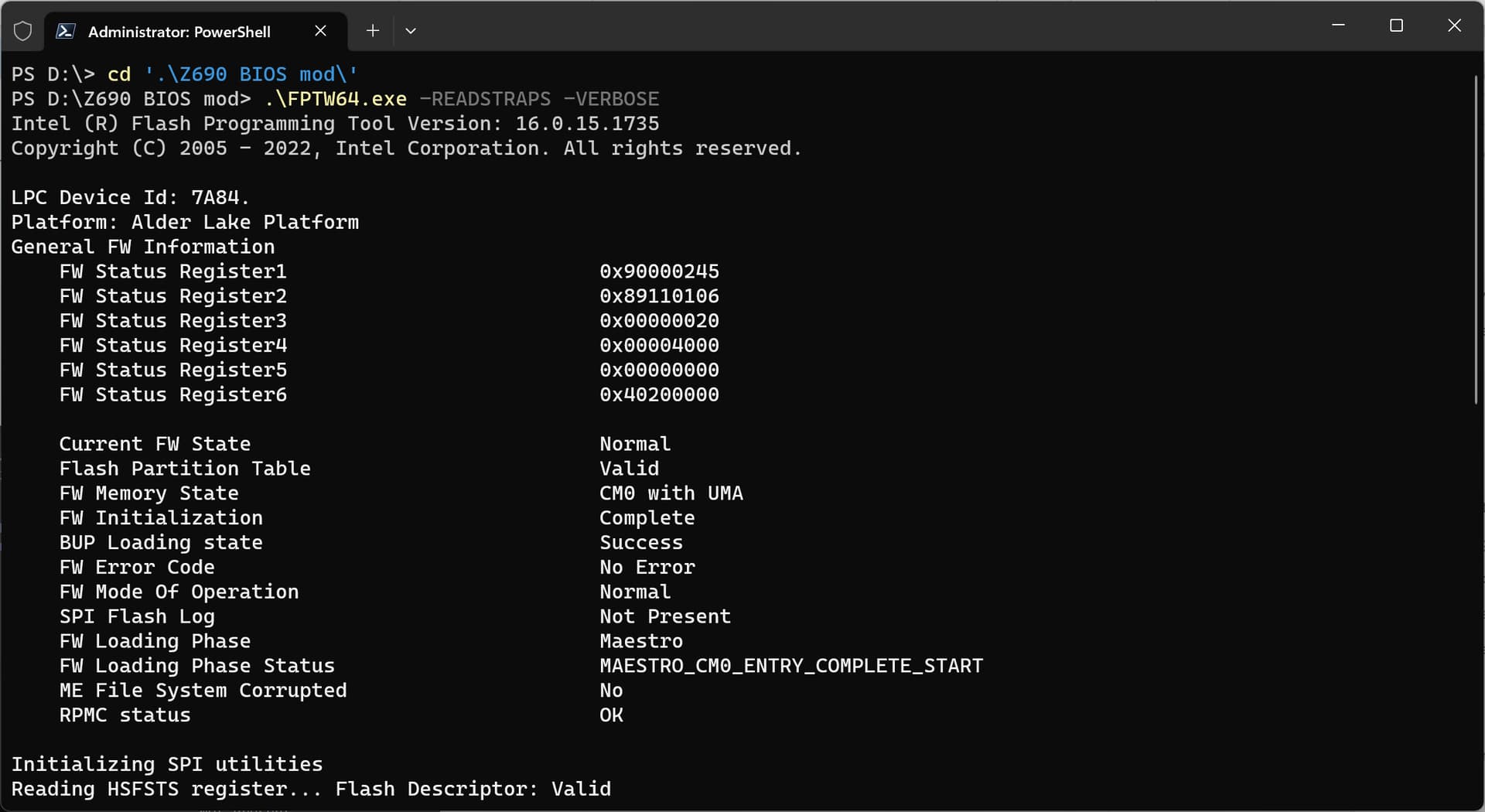
Back in Windows, confirm that this worked by opening an elevated (as administrator) PowerShell window (or command prompt window).
Navigate to your work folder and issue this command.
.\FPTW64.exe -READSTRAPS -VERBOSE
Look for the line “FW Mode Of Operation”. It should read “Unsecured mode by H/W jumper”.
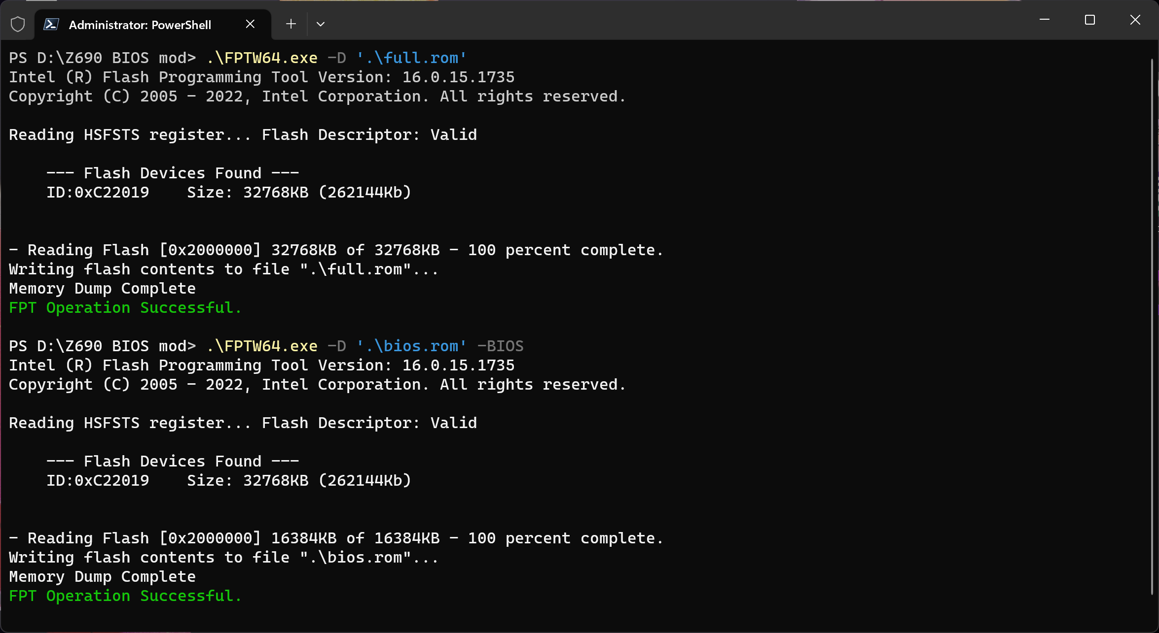
- Create a dump of the entire flash chip (this will be your backup, in case something goes wrong), and then create a BIOS dump file.
.\FPTW64.exe -D '.\full.rom'
.\FPTW64.exe -D '.\bios.rom' -BIOS
Ensure that both commands returned “FPT Operation Successful.” and that the file size is 32 MiB exactly for full.rom and 16 MiB exactly for bios.rom. - These next steps are very important, as without it, you may not be able to recover the BIOS, in case, something goes wrong!
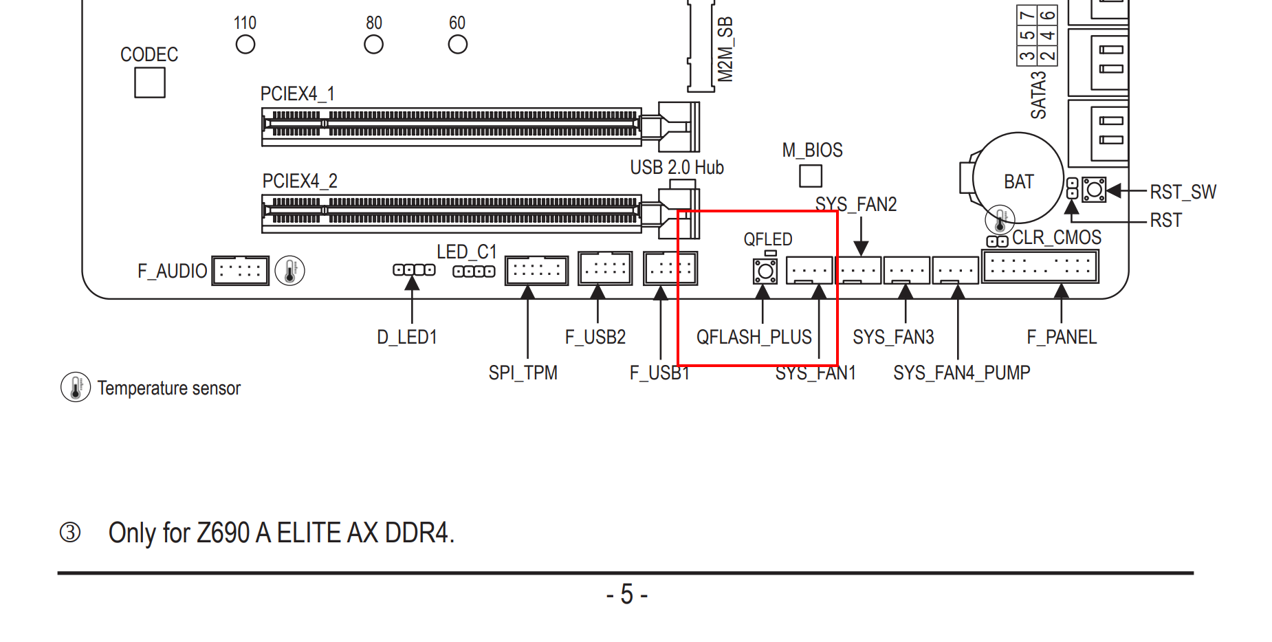
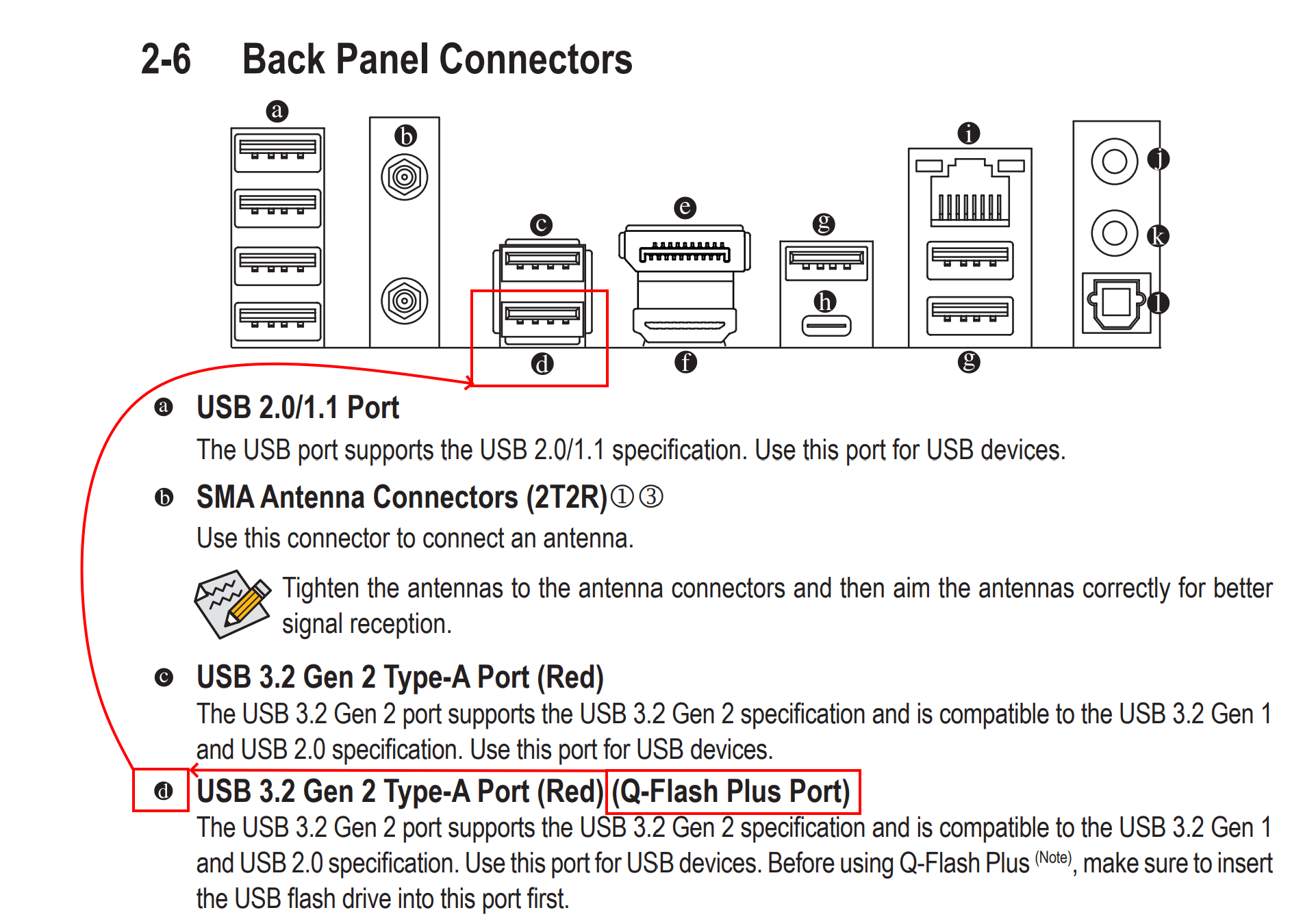
Verify, that your mainboard has the QFlash Plus feature. The manual should mention it.
Take note of where the QFlash Plus button is located on the mainboard. Also take note of the QF LED which should be right next to it.
Look for the section that describes the back panel connectors.
Take note of where the USB port for QFlash Plus is. It will be labeled “BIOS” on the back panel.
Insert the flash drive into the QF+ USB port.
Copy full.rom to the flash drive and rename it “GIGABYTE.bin”. The spelling is case sensitive.
Shutdown the computer.
Open the PC case and press the QFflash Plus button.
If this works, the PC will turn on, but the monitor will stay dark. Be patient, it takes about 7 minutes. While it is working, the QFlash LED will blink. When it is done, the PC should reset and then boot as usual.
If something else happens, if for instance, the computer switches on and then right off again, then it didn’t work. Try different flash drives. In my experience, QF+ is very picky when it comes to flash drives. I had to try 3 or 4 drives until I found one that worked.
Ensure, that it is FAT32 formatted, not ExFAT or anything else. Ensure that “GIGABYTE.bin” is in the root folder of the flash drive and is named correctly.
If this didn’t work, you cannot proceed, because you may not be able to recover the BIOS, in case, something goes wrong!
This concludes the preparations.
2. Revealing hidden BIOS settings
2. Revealing hidden BIOS settings
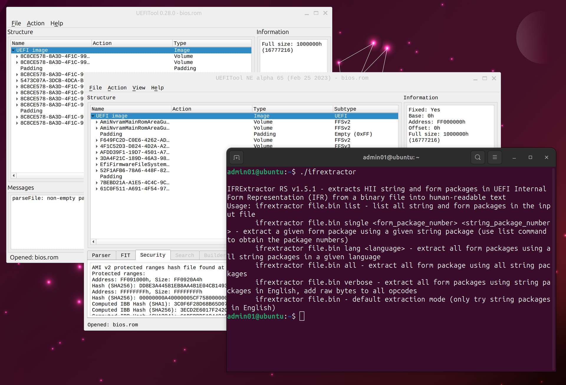
- Open bios.rom in UEFITool NE.
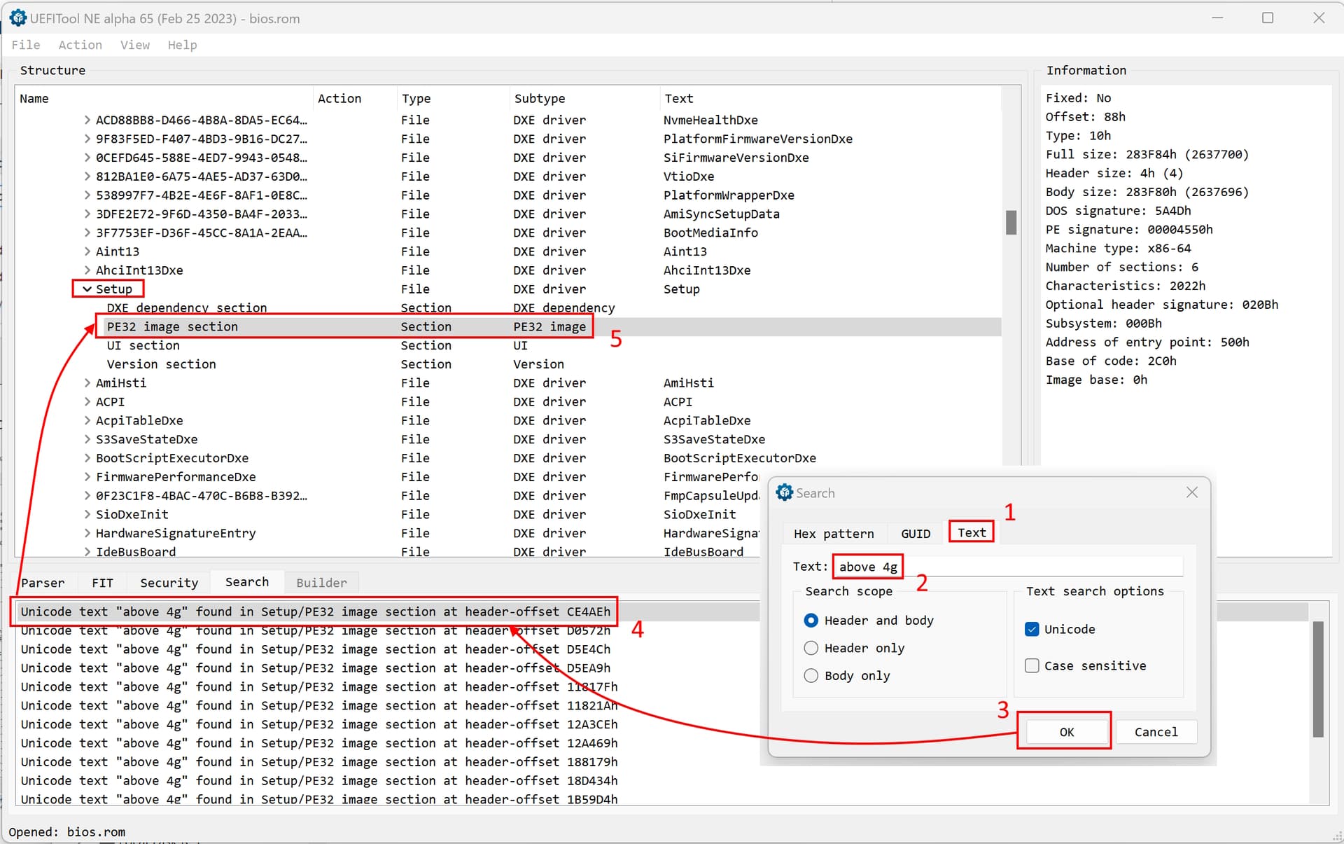
- Search for a known BIOS setting, like “Above 4G” as text.
In the search window, look for a result that contains “Setup/PE32”. It should be the first result.
Double click on the search result and you will get to “PE32 image section” in the main window. Make sure that it is underneath of “Setup”.
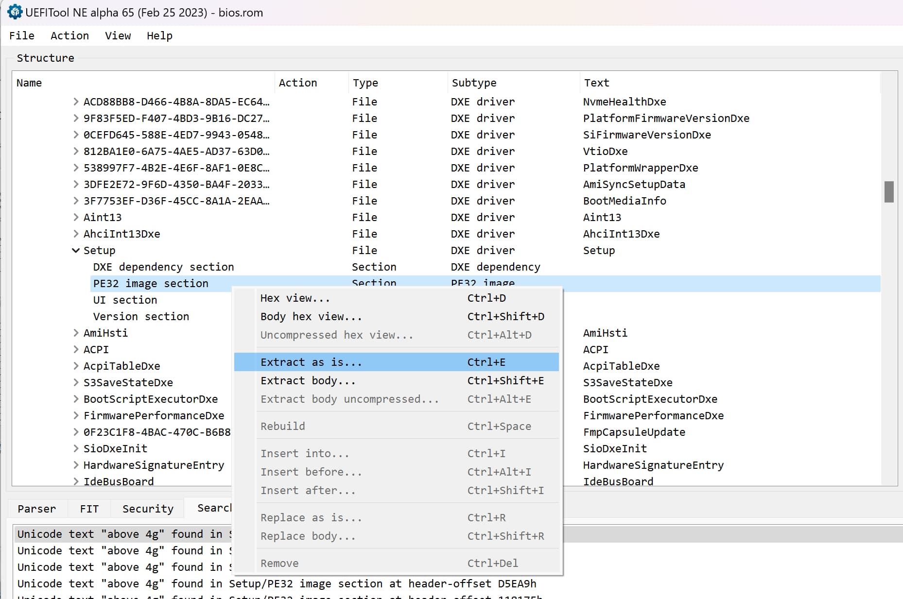
Right click and choose “Extract as is”. Save the file in your work folder.
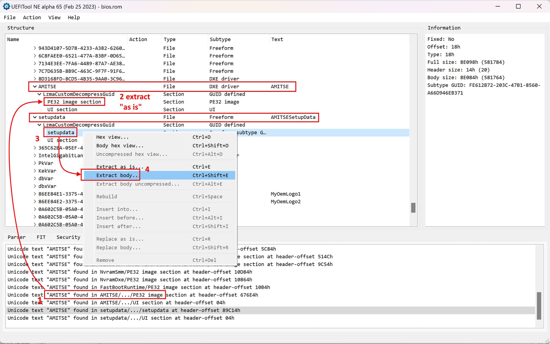
- Next, search for “AMITSE” and look for a search result “AMITSE found in AMITSE/…/PE 32 Image”.
Export the AMITSE PE32 image section “as is” just like before. - Right below, there should be “setupdata” with “AMITSESetupData” in the text column.
Expand it and expand “Lzma…” and extract “setupdata” as body. If it is not there, search for it.
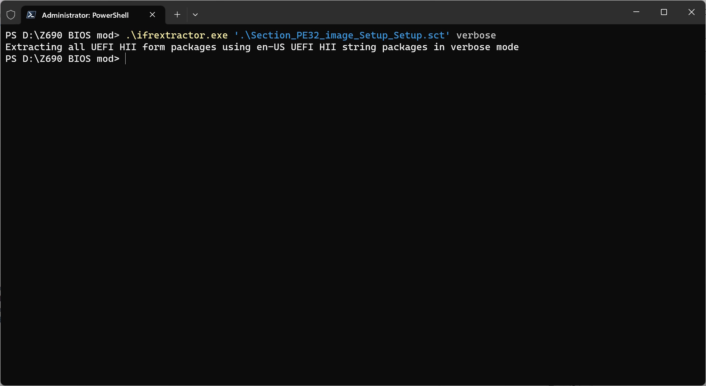
Keep UEFI Tool open. In PowerShell, run the following command.
.\ifrextractor.exe '.\Section_PE32_image_Setup_Setup.sct' verbose
You should now have these 4 files in your work folder:
Section_PE32_image_Setup_Setup.sct
Section_PE32_image_AMITSE_AMITSE.sct
Section_Freeform_subtype_GUID_setupdata_setupdata_AMITSESetupData_body.bin
Section_PE32_image_Setup_Setup.sct.0.0.en-US.ifr.txt
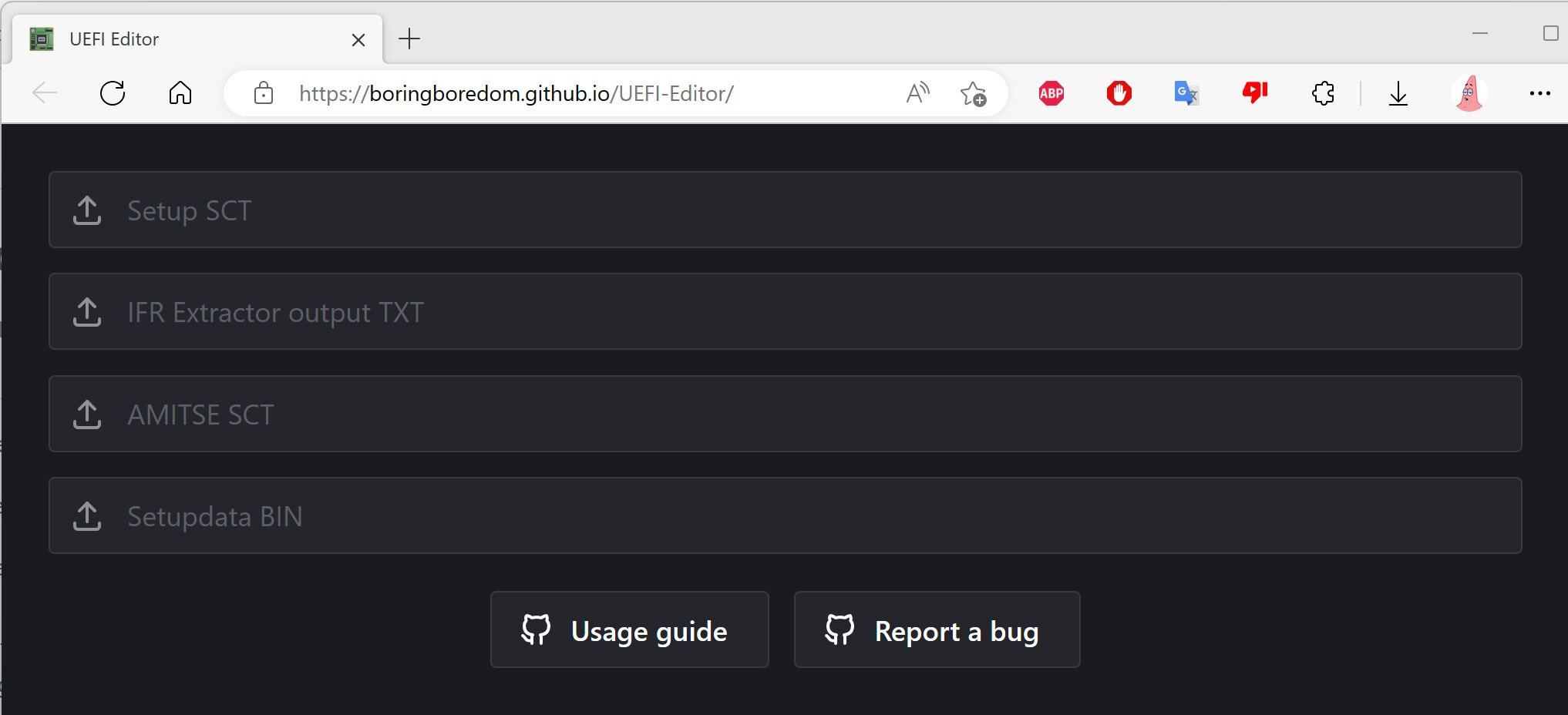
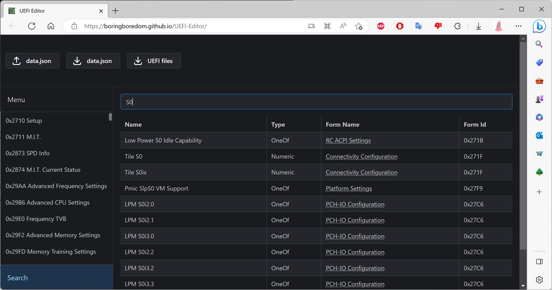
In a web browser, open UEFI Editor and load all four files.
You can now see all the hidden settings that the BIOS offers.
Look around and find the setting that you like to change. I am looking to enable S0 aka Modern Standby, which is hidden and disabled by default (because it is not a laptop computer after all).
When you have decided, what you would like to change, proceed to the next step.
3. Getting ready to change hidden BIOS settings
"3. Getting ready to change hidden BIOS settings
- Before you proceed with the next step, beware that a lot of common sense and a lot of research is needed when you decide to change hidden settings.
Some settings are hidden, because the mainboard does not support them. You could fiddle around with the settings for PCIe Root Port 28, but the board does not have 28 PCIe root ports.
Be mindful of dependencies between different settings. For instance, if you enable Resizable Bar, you also need to enable Above 4G Decoding. If you forget that, the computer won’t boot! If you change settings in the BIOS setup menu, these dependencies are taken care of automatically, but with the method shown here, you have to take care of them. Sometimes, dependencies will be indicated in the help text, sometimes, they won’t.
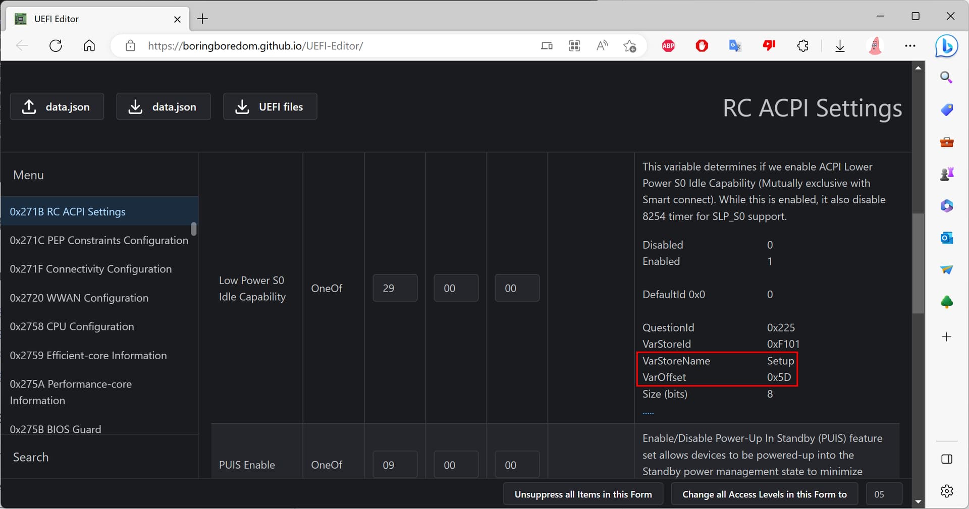
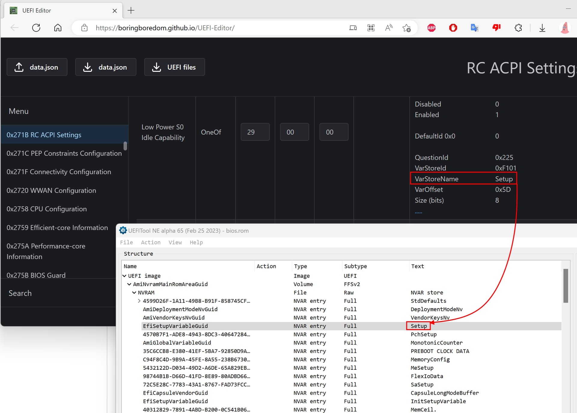
A lot of settings are hidden, because they are for debugging purposes only, and they have no use on a computer that is for gaming or for work. - Expand the setting, that you will change and take note of the possible values for the setting. Usually, it is Disabled (0x0) or Enabled (0x1) but some settings have more options.
Also take note of the VarStorName and the VarOffset. The size should always be 8 bits.
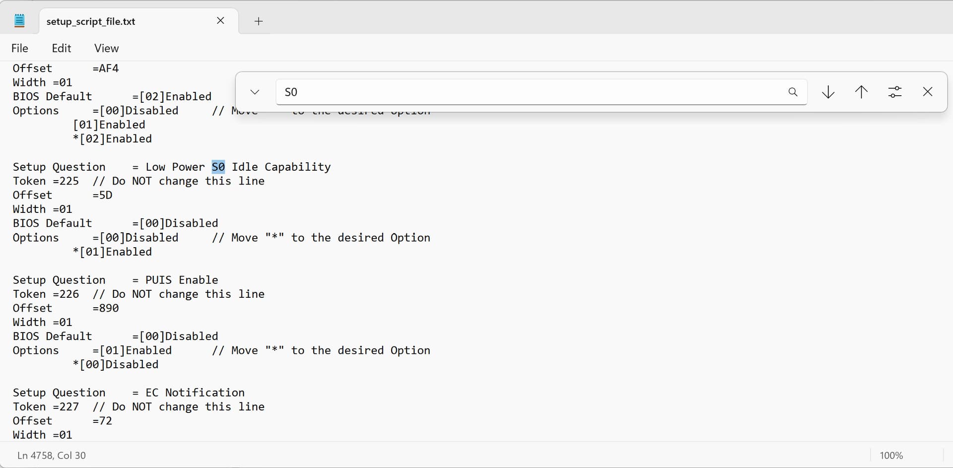
In my case, I will change “Lower Power S0 Idle Capability” from 0x0 (Disabled) to 0x1 (Enabled), the VarStor is “Setup” and the offset is 0x5d.
- Back in UEFITool, scroll to the very top. Locate and expand “AmiNvramMainRomAreaGuid” and expand “NVRAM”.
Now look at the text column, and look for the VarStor that you need. I am looking for “Setup”. Make sure, that the type is NVAR entry.
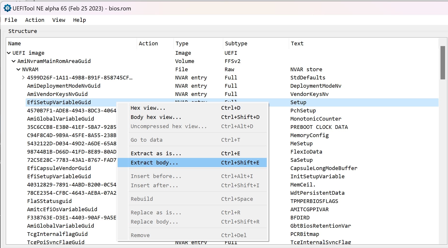
Extract the variable as body.
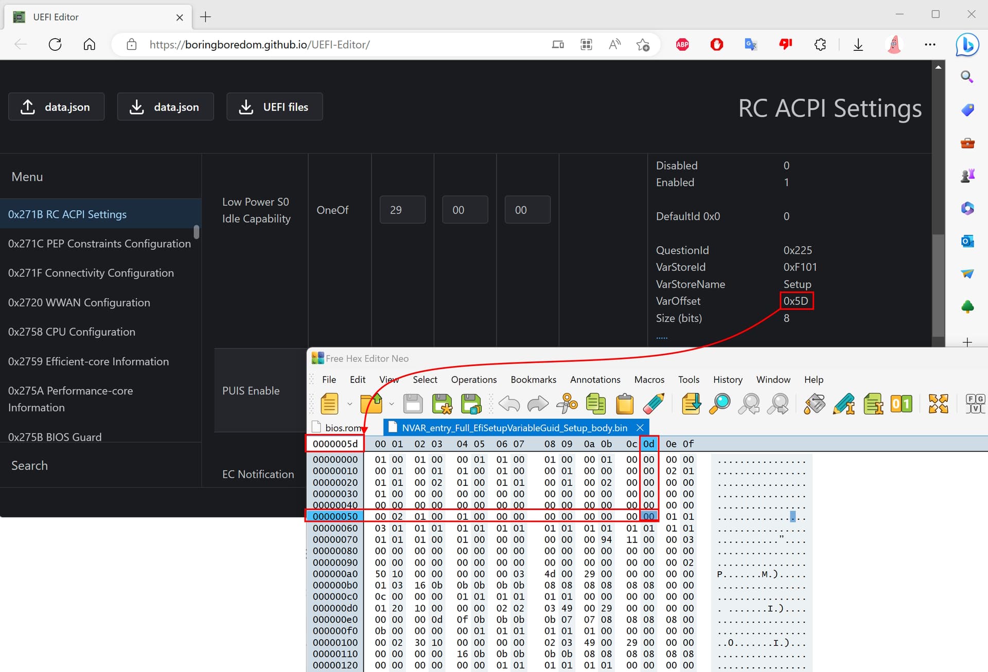
- Open the resulting file in your hex editor.
Navigate to the offset that is indicated in UEFI Editor. Here, I am looking for offset 0x5d.
This concludes part 1. From here, you have two options. If you would like to modify the Optimized Defaults, proceed with Changing hidden BIOS settings - Optimized Defaults. If you would like to modify your saved profile, proceed to Changing hidden BIOS settings - Profile.
4. Changing hidden BIOS settings - Optimized Defaults
4. Changing hidden BIOS settings - Optimized Defaults
- You only need to do one part, Changing hidden BIOS settings - Optimized Defaults OR Changing hidden BIOS settings - Profile, not both!
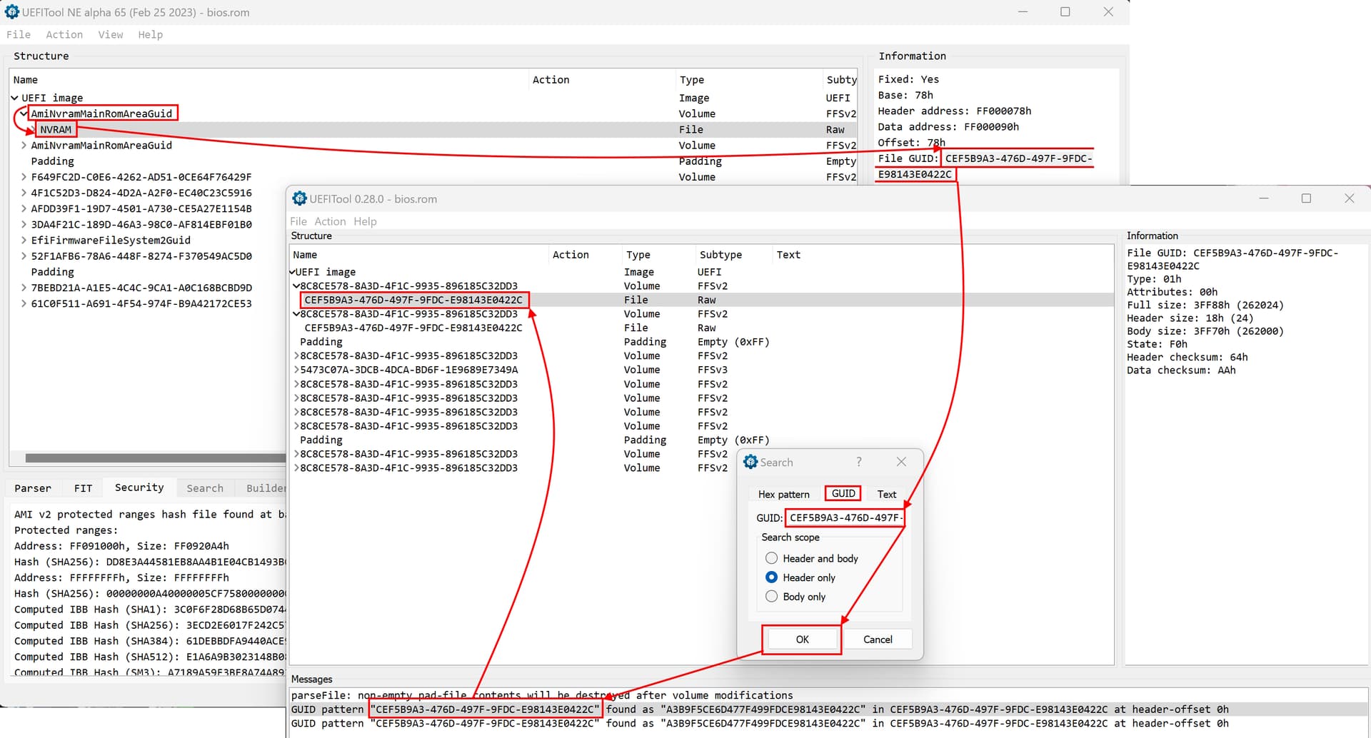
- In UEFI Tool 0.28.0, open bios.rom. You should still have bios.rom open in UEFI Tool NE.
- In UEFI Tool NE, locate “AmiNvramMainRomAreaGuid”.
- Expand it and locate “NVRAM”
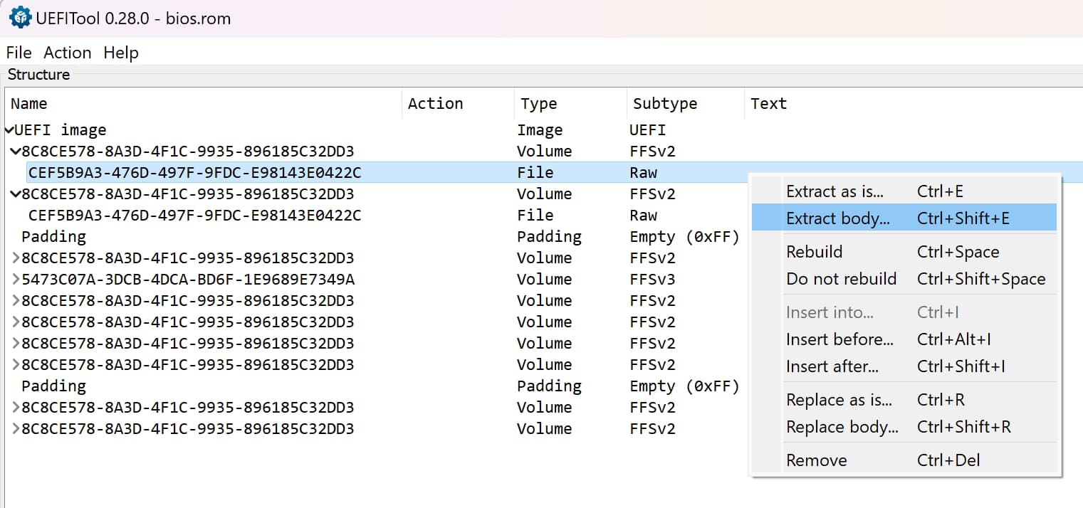
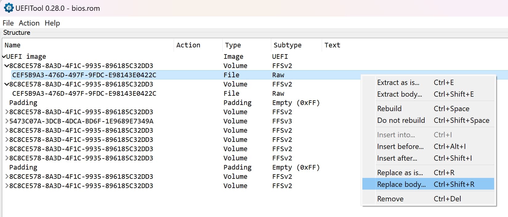
- Look at the Information box and note its File GUID. Here, it is “CEF5B9A3-476D-497F-9FDC-E98143E0422C”
- In UEFI Tool 0.28.0, open a search window and switch it to GUID. Search for the GUID.
- Note that, in the screenshot it is found twice. If it is found twice, note that for later.
- Still in n UEFI Tool 0.28.0, right click on the file you just found, and choose extract body. Its type should be “File” and its Subtype “Raw”.
- Name the file NVRAM.bin, and open it in hex editor. Keep UEFI Tool 0.28.0 open.
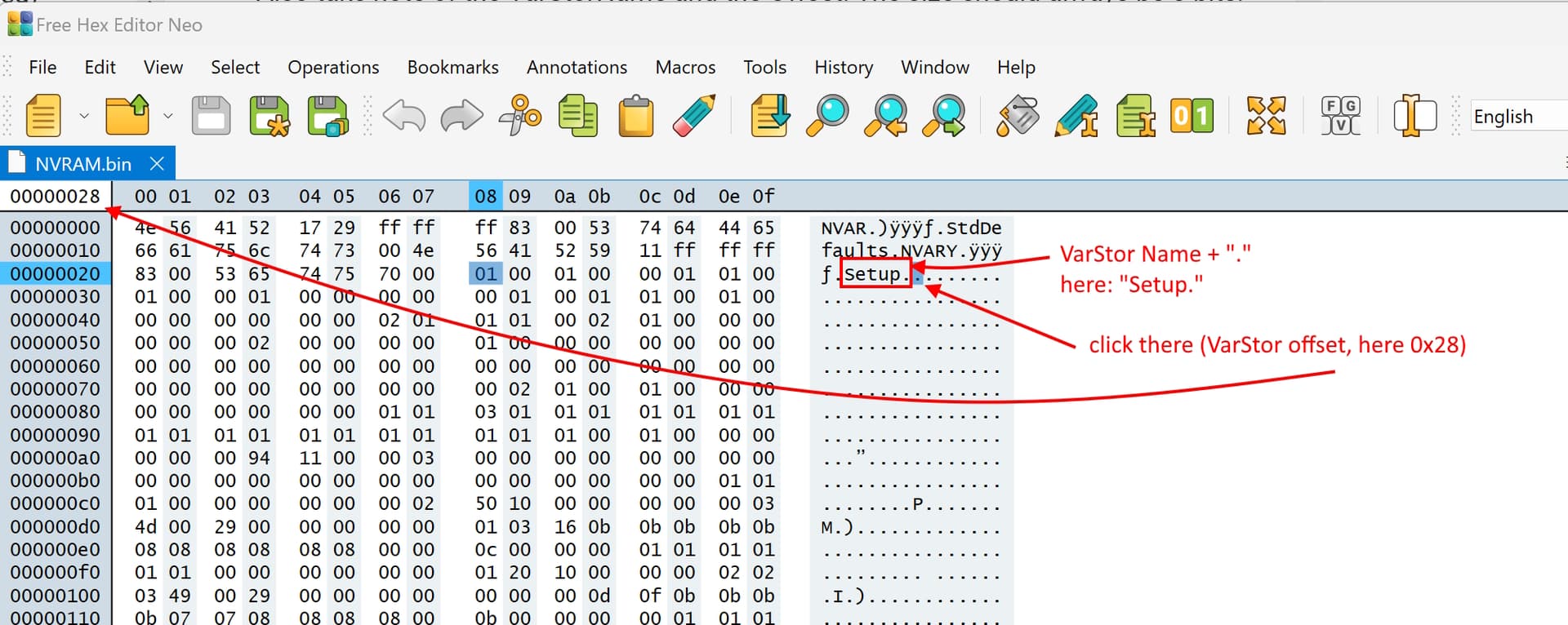
- In hex editor, you should see “StdDefaults” at the very beginning of the file.
- Locate the variable (VarStor) that you need. If it is “Setup”, you are already at the right location, because it should be at the beginning of the file. If you are not looking for “Setup”, search for the VarStor name, as a string. For example: “PchSetup”.
- Once you have found the VarStor that you need, locate its offset.
After the variable name, there should be a dot. Click on the symbol/byte after it. This is the base offset for the variable (=VarStor) (here: 0x28).
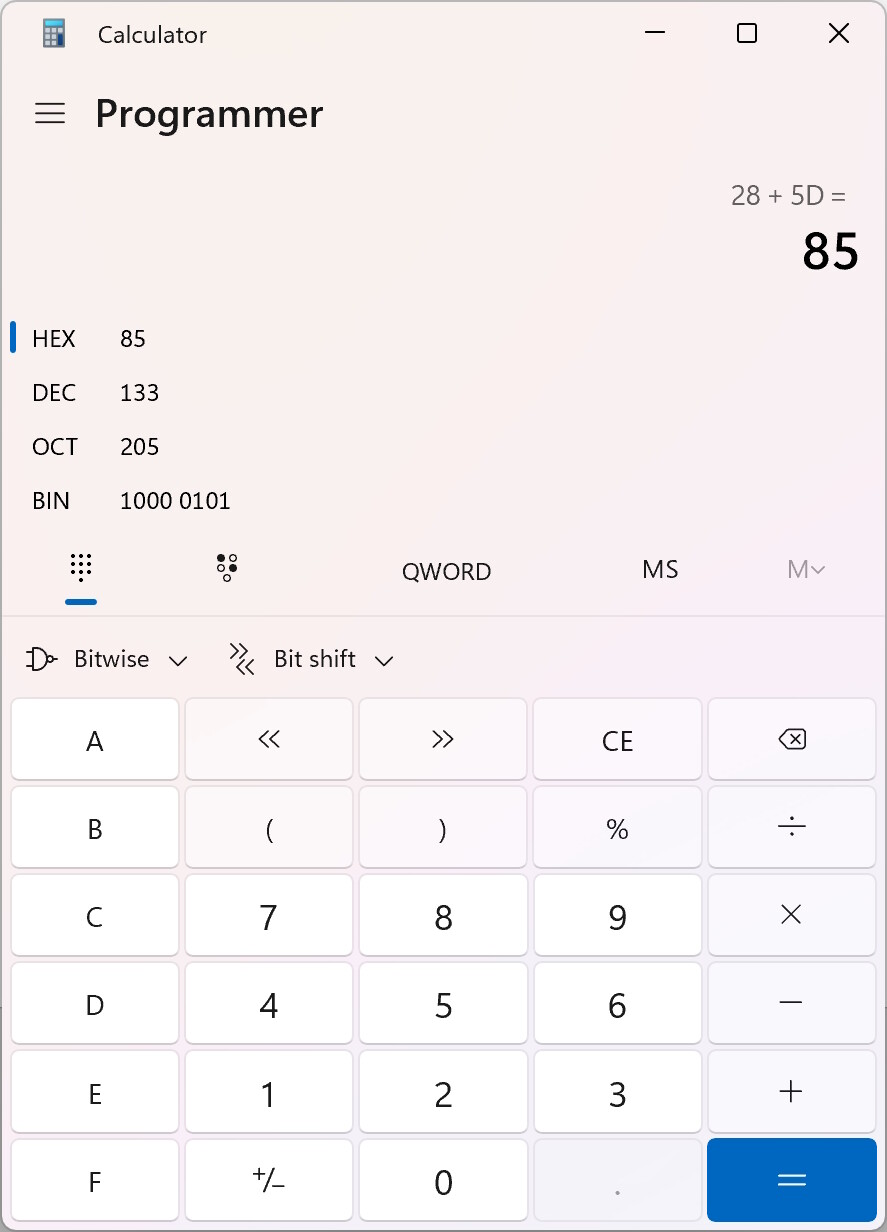
- Now, a little math is needed, which you can do with a calculator, like Windows calculator, if you switch it to “Programmer” and hex.
You now should have two things:
The offset of the VarStor in NVRAM.bin
The VarOffset of the setting you would like to change.
The formula is:
Location (offset) of setting in NVRAM (NVRAM.bin) = VarStor offset + VarOffset
Example:
Let’s remember that I want to change “Lower Power S0 Idle Capability” and its VarStor name is “Setup” and its VarOffset is 0x5d.
Also, Setup’s offset in NVRAM.bin is 0x28.
Location (offset) of setting in NVRAM (NVRAM.bin) = VarStor offset + VarOffset
Location of "Lower Power S0 Idle Capability" = 0x28 + 0x5d
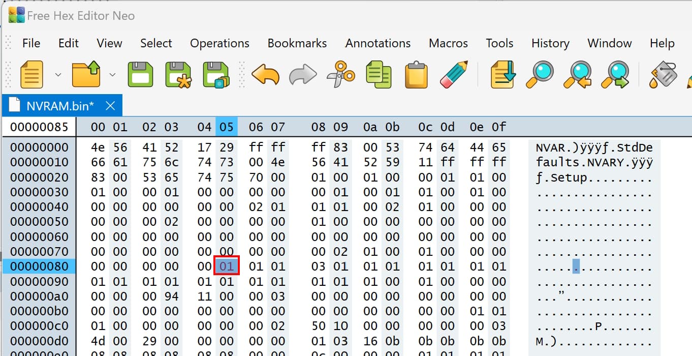
0x28 + 0x5d = 0x85
In Windows calculator, I enter, as hex, 28 + 5d = 85 (0x85)
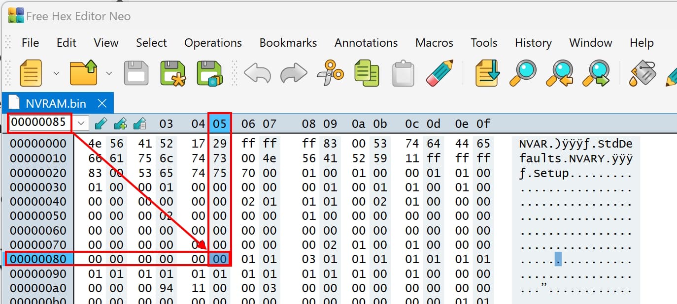
- Enter the result in hex editor in the area for the offset and it will get you to the exact location, that you need to change.
- You should now have two hex editor windows open and in both windows, you have located the setting that you want to change.
the compare the bytes before or after it. They should be exactly the same.
- In NVRAM.bin, change the setting you would like to change. Here, it is the byte at offset 0x85.
- Save NVRAM.bin as NVRAM_modded.bin.
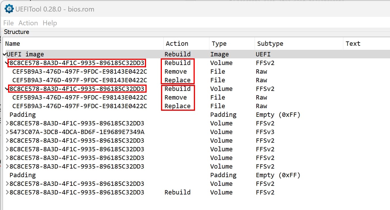
- Back in UEFI Tool 0.28.0, exactly at the same spot where you extracted NVRAM.bin, right click and choose “Replace body” and choose NVRAM_modded.bin.
- If you found two results earlier, replace the other as well.
- Now click on “File” \ “Save image file” and save it as “bios_mod.rom”.
Proceed with “Flashing modded BIOS to flash chip”.
5. Changing hidden BIOS settings - Profile
5. Changing hidden BIOS settings - Profile
- You only need to do one part, Changing hidden BIOS settings - Optimized Defaults OR Changing hidden BIOS settings - Profile, not both!
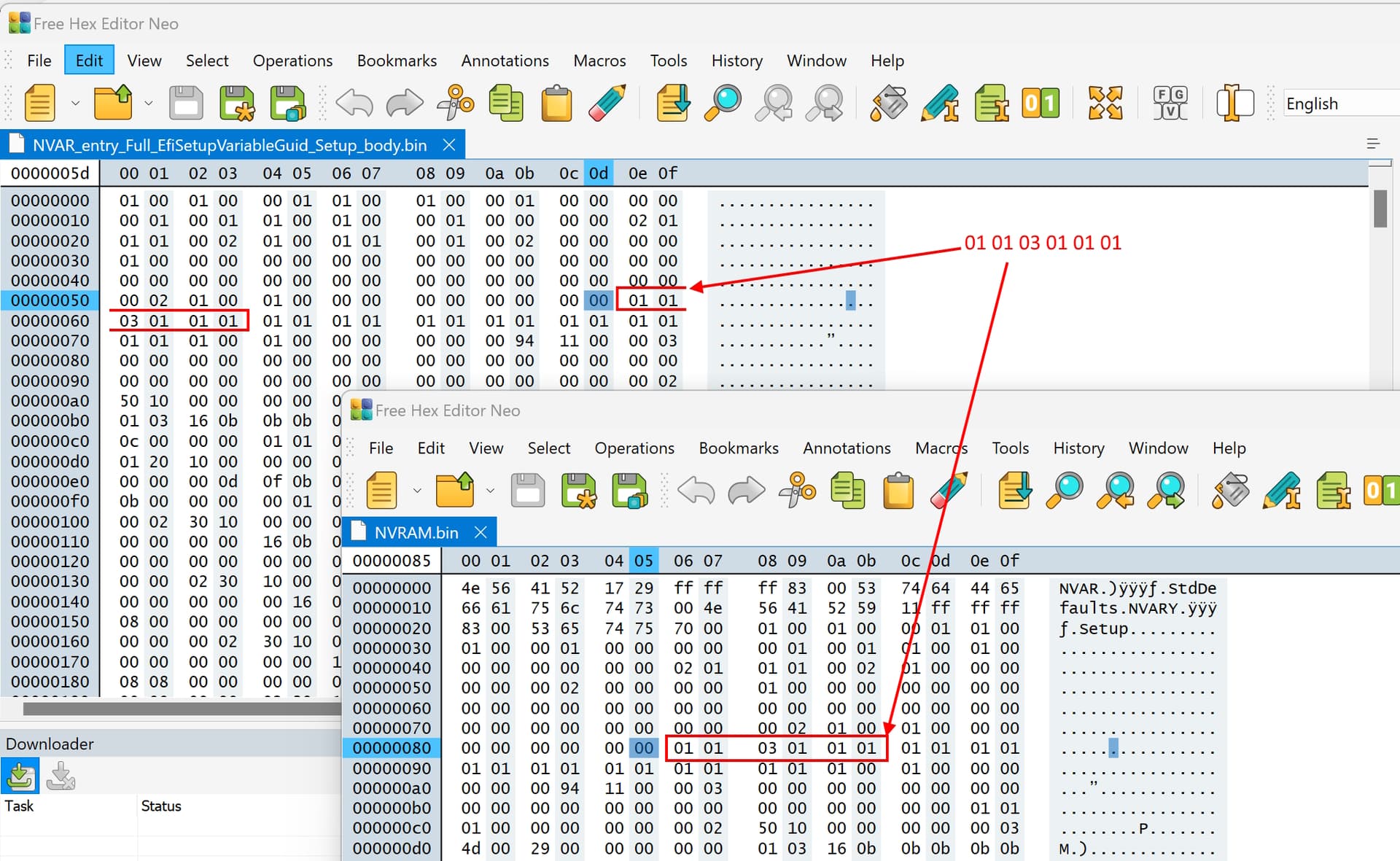
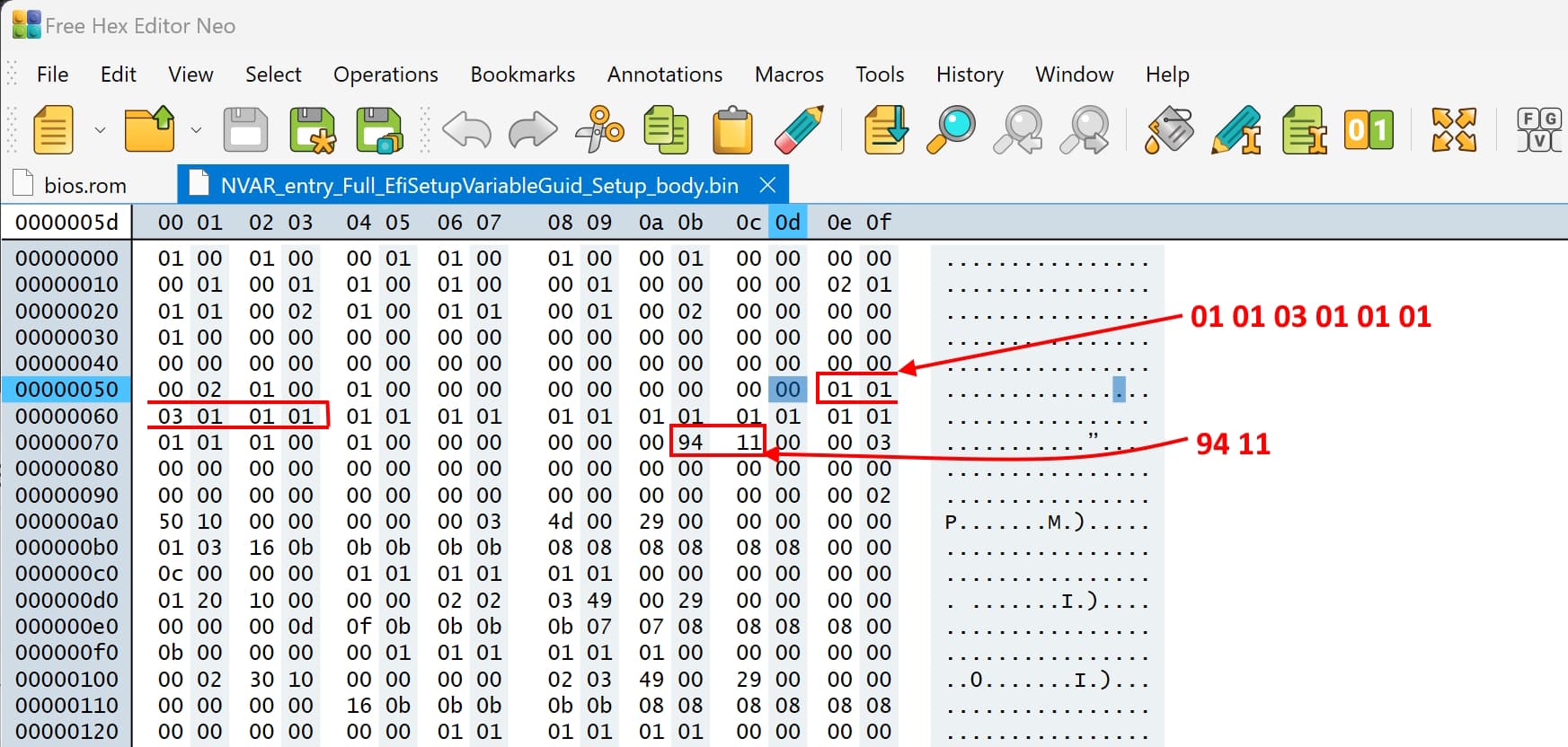
- Look for recognizable patterns close to the offset. It can be before or after. It should not be 00 00 00, or 11 11 11 or ff ff ff. It should be a different, distinct pattern.
For my setting (S0 enable byte), I am noting that the bytes right after it, are: “01 01 03 01 01 01”. I also see “94 11” a little bit after that.
Take note of the pattern.
Keep this file open, and then open bios.rom in hex editor, in a separate window.
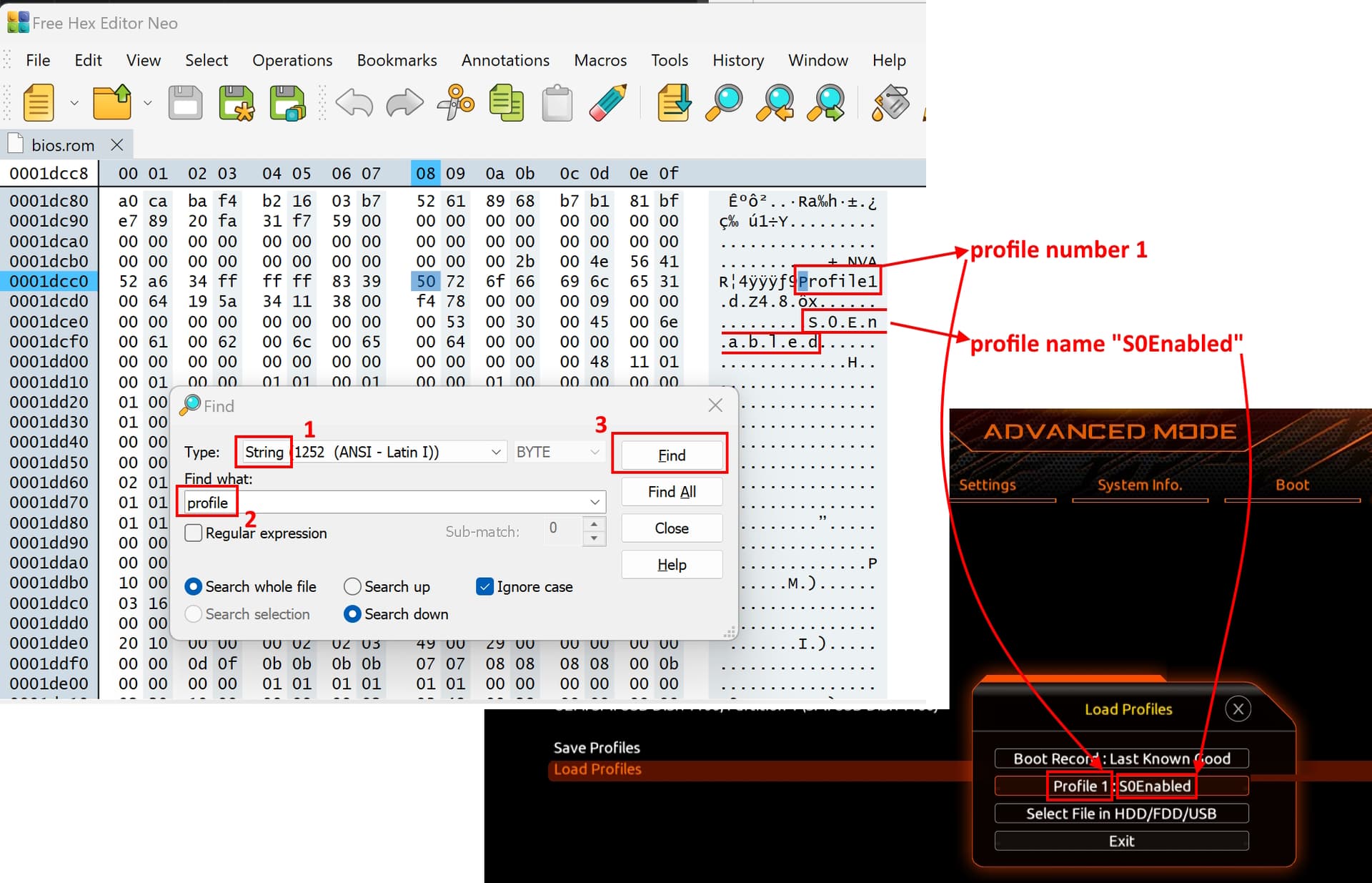
Search (as text/string) for “profile”
Find the profile that matches the number your profile was saved as. Also confirm that the name that you gave your profile shows up.
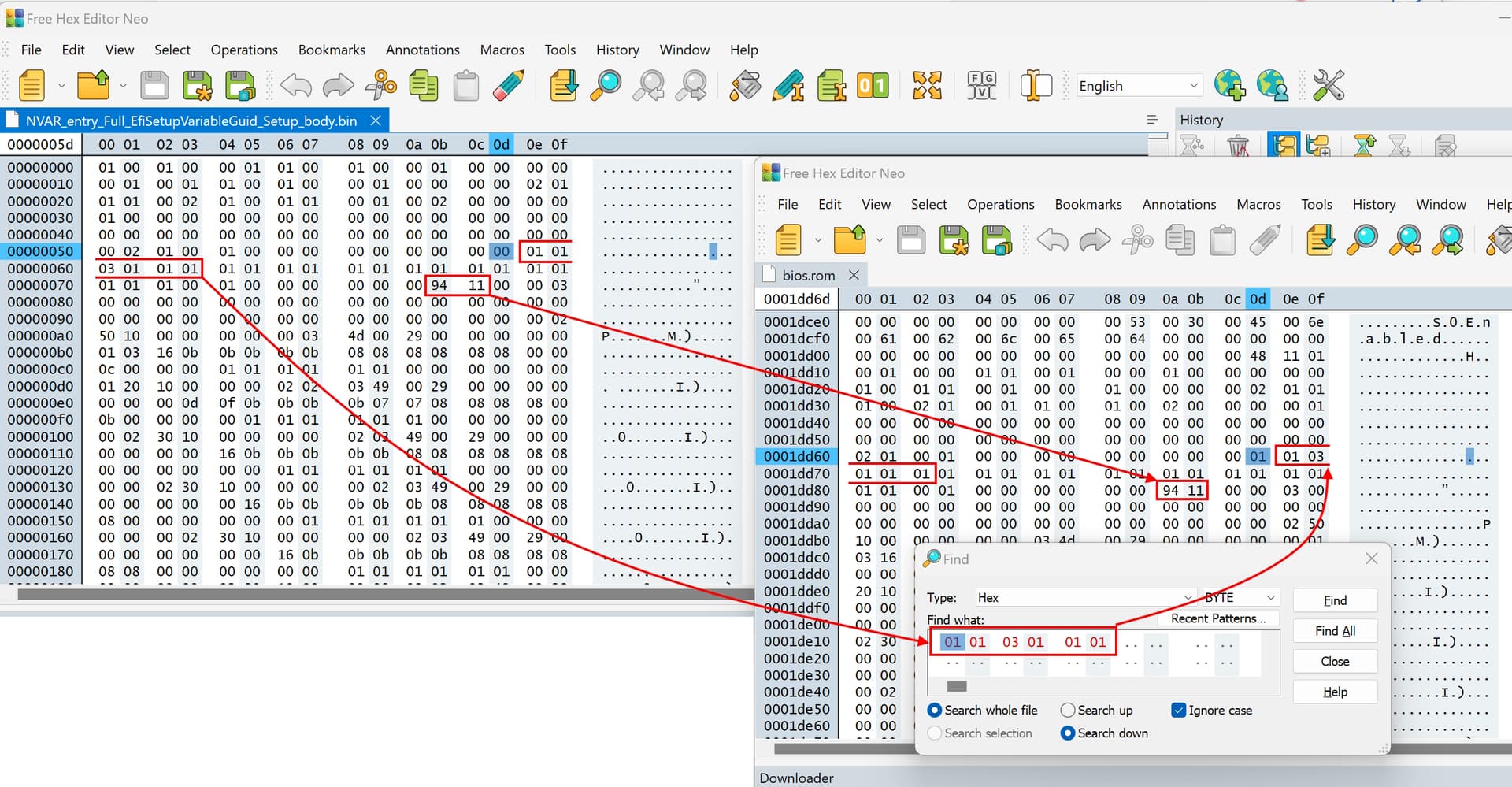
Switch the search to hex and search for the pattern you previously noted. I will search for “01 01 03 01 01 01”.
Once you have located the byte you are looking for, open both windows next to each other and compare the bytes before and after.
See if they match. If they do, you have found the right location.
I also see the bytes “94 11” in the exact location that I expect them to be.
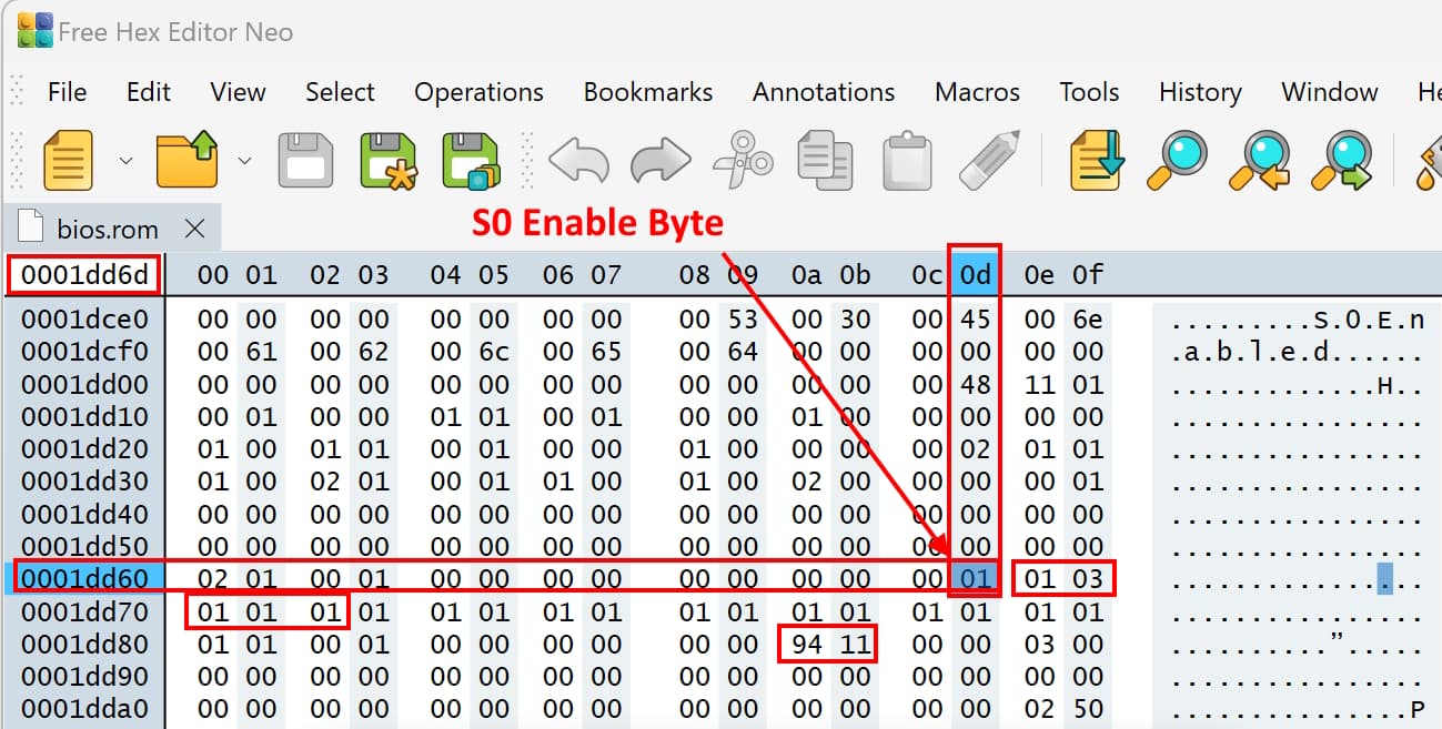
The byte that I need to edit is right before the "“01 01 03 01 01 01” bytes. In my case, it is at offset 0x1dd6d.
Once you are confident that you have found the right location, set the value to what you want it to be. In my case, I will set it to 0x01 to enable S0 Modern Standby.
Save the file as a new file. Name it “bios_mod.rom”.
6. Flashing modded BIOS to flash chip
6. Flashing modded BIOS to flash chip
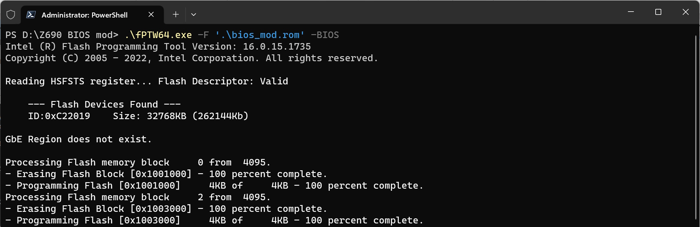
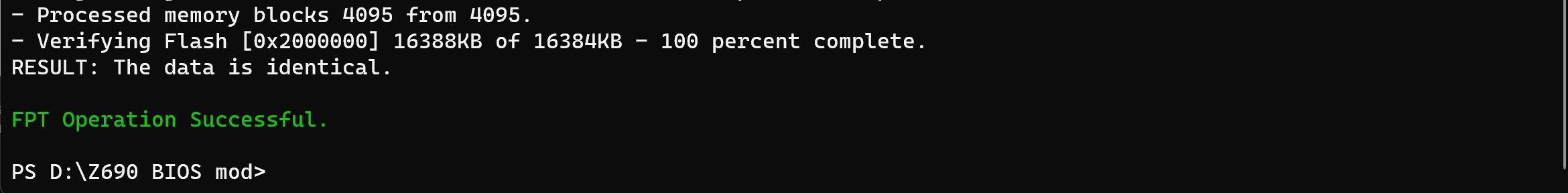
- Use fpt again to flash the modded BIOS back onto the flash chip.
.\fPTW64.exe -F '.\bios_mod.rom' -BIOS
7. Applying changes
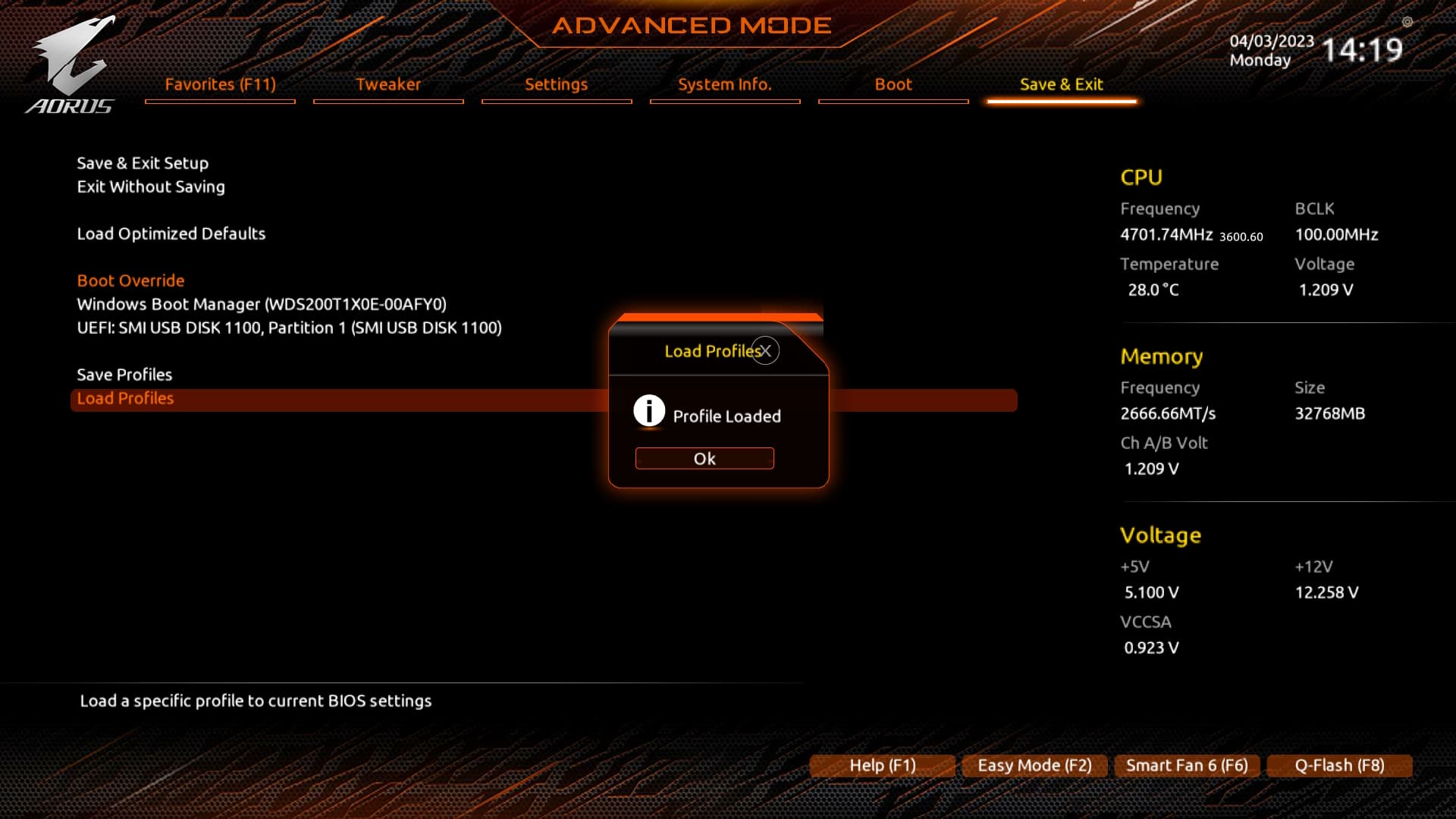
- Reboot and enter BIOS.
- Load your profile, or load Optimized Defaults, depending on which route you took.
- Save the new settings and exit. Ater the reboot, the new settings will be active.
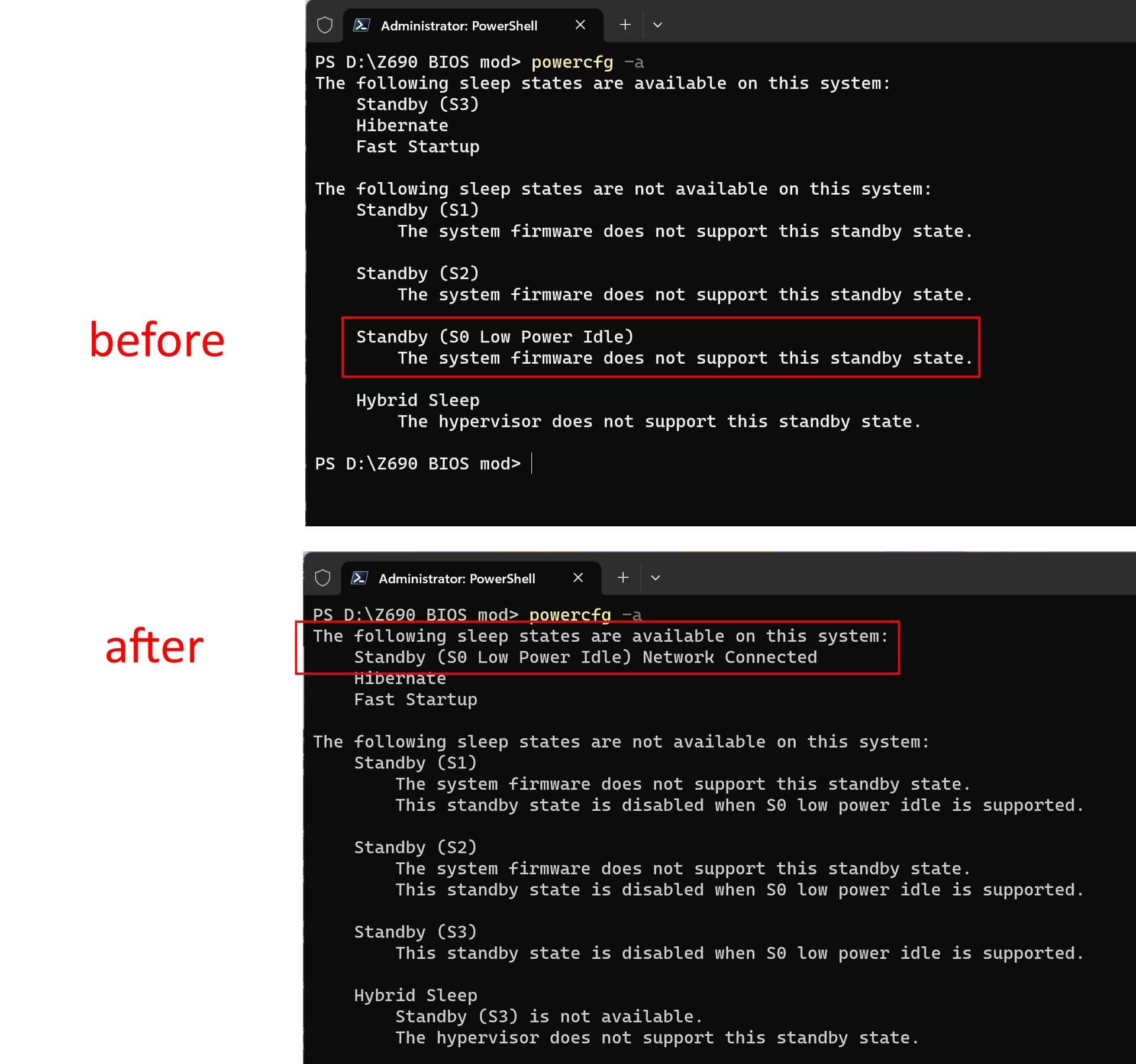
- Confirm, that the new settings are working. The method will vary, depending on what you changed. For checking for S0, I can use
powercfg -a
8. Re-enabling Security measures
This final step is very important! In one of the first steps in this guide, I showed how to disable SPI flash protections. This was needed to create a backup dump and to flash the modded BIOS using FPT.
Intel Management Engine (CSME) was also disabled. This is an insecure configuration and it is undesirable in the long run.
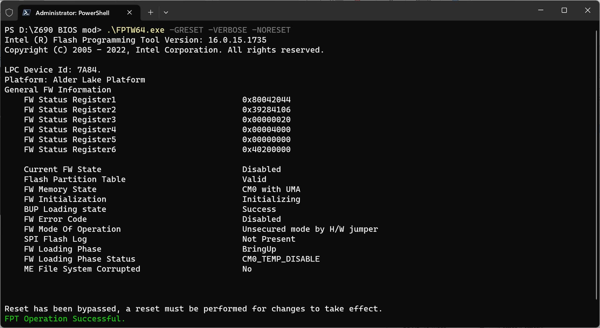
To re-enable all protections, issue the global reset command. This will cause a restart of the Management engine, the next time the computer reboots, and put the system back into a secure operating mode.
- Use FPT to reset (CS)ME
.\FPTW64.exe -GRESET -VERBOSE -NORESET
- Now reboot the system.
- Verify that this worked
.\FPTW64.exe -READSTRAPS -VERBOSE
Look for “FW Mode Of Operation”. It should read “Normal”.
9. Alternative method
9. Alternative method
A simpler way of achieving this would be by using AMI’s SCP tool (version 5.03.1115 for instance). The issue with this tool is that I don’t have a link for it. If one had access to SCP, one could.
- write all questions (as they are called here) to file.
.\SCEWIN_64.exe /o /s '.\setup_script_file.txt' /a
- Open setup_script_file.txt and look for the setting that needs to be changed.
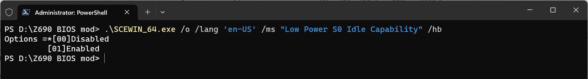
Note the name of the question. Here “Low Power S0 Idle Capability”.
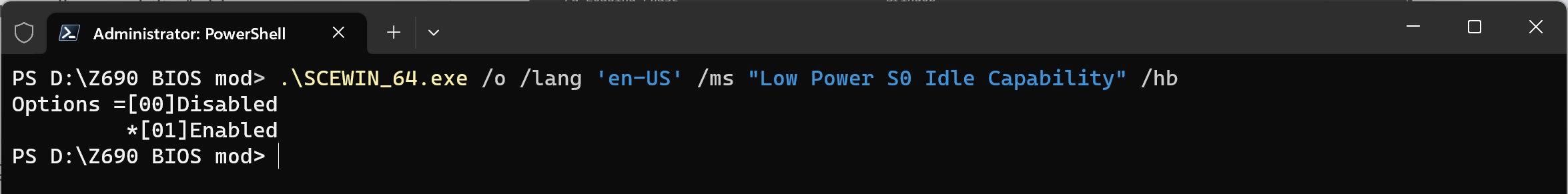
- check the question’s current value. “*” next to “[00]Disabled” indicates S0 is currently disabled.
.\SCEWIN_64.exe /o /lang 'en-US' /ms "Low Power S0 Idle Capability" /hb
- change the current setting (value) like so. here, S0 would be enabled by setting its value to “0x1”.
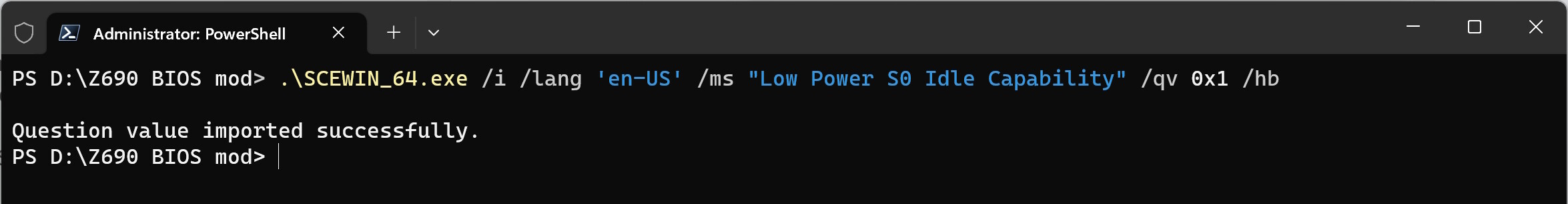
.\SCEWIN_64.exe /i /lang 'en-US' /ms "Low Power S0 Idle Capability" /qv 0x1 /hb
- And confirm the change by querying the value again.
.\SCEWIN_64.exe /o /lang 'en-US' /ms "Low Power S0 Idle Capability" /hb
- or, one could change the default value and then load defaults in BIOS setup with the “/ds” switch
.\SCEWIN_64.exe /i /lang 'en-US' /ms "Low Power S0 Idle Capability" /qv 0x0 /ds /hb
- or, if multiple values need to be changed, it would be more efficient to edit setup_script_file.txt directly by placing the asterisk in the appropriate line,
- and then apply all changes to the BIOS using the import command (“/i”).
.\SCEWIN_64.exe /i /s '.\setup_script_file_S0_enable.txt' /ds /r
- In any case, a reboot would be required for changes to take effect.
10. Using Linux, open source software only (no Intel FPT, AMI SCE, etc.)
10. Using Linux, open source software only (no Intel FPT, AMI SCE, etc.)
For testing, I used Ubuntu 23.04 (daily build, Apr 4, 2023). In general, follow the guide, but deviate from it as follows:
- Start with disabling Secure Boot
Verify that Secure Boot is really off. If the Secure Boot mode is “Deployed”, it will be switched back on, when you turn it off, save settings and reboot. You need to set it from “auto” to “advanced”, then then exit Deployment Mode and set the mode to Setup. Then turn off Secure Boot
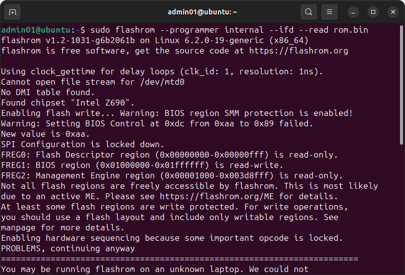
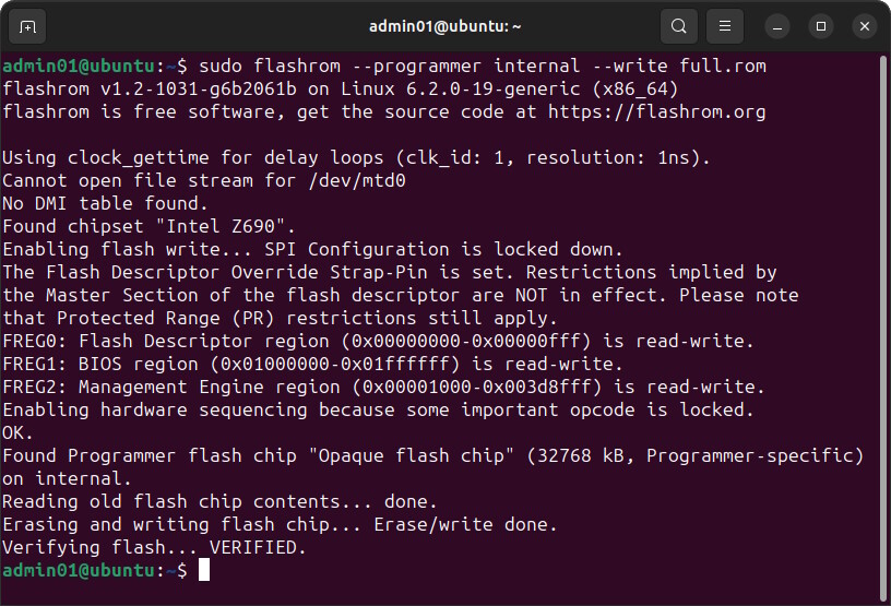
- Instead of using FPT, use flashrom for dumping and flashing
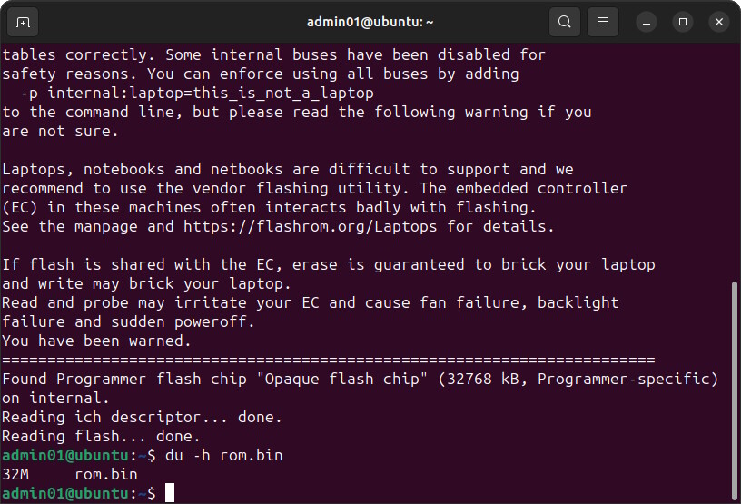
In my case, I needed Dasharo’s version because the original flashrom did not find the flash chip. However, beware, even though, even though flashrom supposedly can read and interpret the flash descriptor with " the “–ifd” switch, I was unable to write just the BIOS region. I always had to write the entire flash chip to successfully write the modded BIOS.
When I tried
sudo flashrom --programmer internal --ifd --write bios_region_only.rom --image bios
It would complain that the image was to small (image is 16 MiB, flashrom was expecting 32 MiB) and refuse to write the image.
When I tried to supply the full rom image, but only write the BIOS region, like so,
sudo flashrom --programmer internal --ifd --write full.rom --image bios
flashrom wrote the image but the system ended up not booting and I had to recover using QF+.
Always write the full rom image! Do not use the ‘–image bios’ switch!.
building flashrom:
sudo apt update
sudo apt install git build-essential pkg-config libpci-dev udev
git clone https://github.com/Dasharo/flashrom.git -b dasharo-release
cd flashrom
sudo make install
creating a ROM dump
sudo flashrom --programmer internal --ifd --read rom.bin
writing a full ROM image
sudo flashrom --programmer internal --write full.rom
- downloading the other tools
UEFITtool 0.28.0
sudo apt install libqt5gui5
cd $HOME
wget https://github.com/LongSoft/UEFITool/releases/download/0.28.0/UEFITool_0.28.0_linux_x86_64.zip
unzip UEFITool_0.28.0_linux_x86_64.zip -d ./UEFITool0.28.0
cd UEFITool0.28.0
./UEFITool
UEFITtool NE
sudo apt install libqt6widgets6 qt6-wayland
cd $HOME
wget https://github.com/LongSoft/UEFITool/releases/download/A65/UEFITool_NE_A65_x64_linux.zip
unzip ./UEFITool_NE_A65_x64_linux.zip -d UEFIToolNE
cd UEFIToolNE/
ifrextractor
cd $HOME
wget https://github.com/LongSoft/IFRExtractor-RS/releases/download/v1.5.1/ifrextractor_v1.5.1_Linux.zip
unzip ./ifrextractor_v1.5.1_Linux.zip
chmod +x ./ifrextractor
You can use ghex as your hex editor
sudo apt install ghex
Now you have all the tools needed. - Don’t create a BIOS region only image. When modifying the image, always use full.rom
- To effect the CSME Global Reset, instead of using FPT, shutdown the computer and pull the plug. Leave the computer without power for about one minute.
11. Troubleshooting
11. Troubleshooting
- Verifying that the changes work
If you are having difficulties confirming that the changes you are trying to effect work, or if you know that they did not work, the first step should be to check the UEFI variable (“VarStor”) that contains the setting you are trying to change.
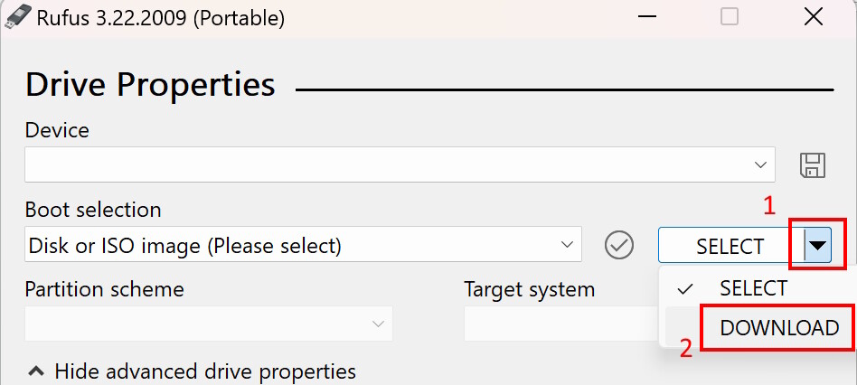
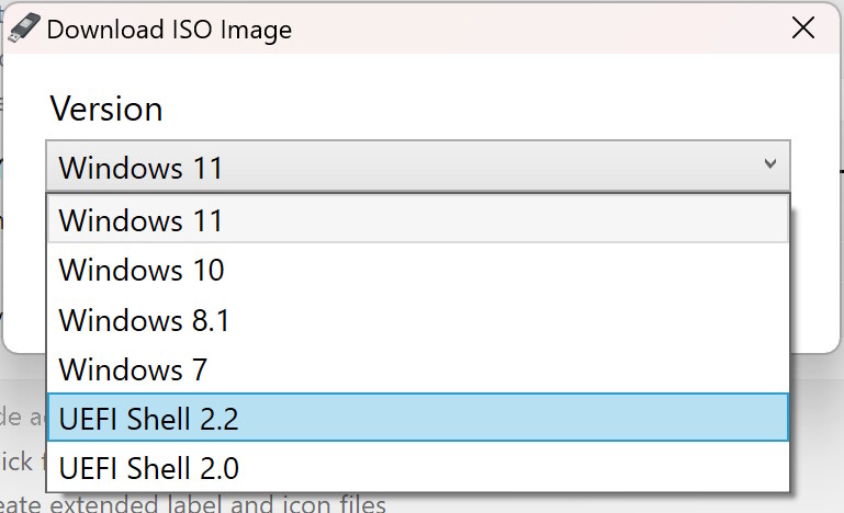
Use Rufus to create a bootable flash drive with UEFI shell.
Choose Download and then UEFI Shell 2.2. Write the ISO to the flash drive.
Download setup_var.efi and put it into the root of your flash drive.
Disable Secure boot and boot from flash drive in UEFI mode.
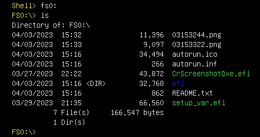
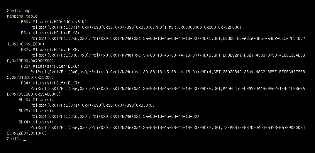
Once in UEFI shell, use “map” to find your flash drive. It will be fs0, or fs1, etc.
Navigate to the mounted flash drive: “fs0:”.
Check its content with “ls”.
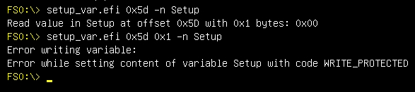
Use setup_var to check the value of the variable corresponding with the setting you are trying to change. Here, I will check the variable "Setup’ and look for offset ‘0x5d’ which is
“Low Power S0 Idle Capability”.
setup_var.efi 0x5d -n Setup
Note, that you cannot change the value directly, because the variable is write protected.
This would change the value, if “Setup” wasn’t write protected.
setup_var.efi 0x5d 0x1 -n Setup
12. Questions, answers
Questions, answers
- What other tools can be used to dump and flash?
Firstly, avoid the following tools, because they do not work:
All tools that verify a checksum or signature will refuse to flash a modified BIOS because changing even a single bit will invalidate the checksum/signature.
These include:
Gigabyte’s @BIOS
Gigabyte’s “Efiflash.efi”
Gigabyte’s QFlash (the version included in the BIOS, not Qflash Plus)
AMI’s Afu tool (AFUWIN, AFUDOS, AFUEFI): The newer versions refuse to flash a modded BIOS. The older versions (with “/GAN” switch) do not recognize the Gigabyte Z690 board’s flash chip.
Secondly, the tools that will flash a modded BIOS, that I know of, are:
The tools that are mentioned above
Intel’s Flash Programming Tool of the Intel CSME tools. (Win, Lin, Efi versions available)
Flashrom (Dasharo fork)
Other tools:
I read that QFlash Plus will flash an unsigned or modded BIOS, but I did not test this.
A hardware flash programmer
A modded version of Gigabyte’s Efiflash (Efiflash_v0.99_mod.efi) should do the job, but I tested only dumping, not writing. You can find it here on the forums.
- The Flash Descriptor Region (FDR) designates the BIOS region as read and write enabled. Is it really necessary to disable all flash protections and disable the Management Engine in the process in order to flash the BIOS region?
Afaik, yes. That or QF+ or a hardware flash programmer, it seems. The default configuration on this board (Gigabyte Z690 Aorus Elite DDR4) is that in the BIOS Control (BIOS_SPI_BC) register, the Lock Enable (LE) bit is set, which prevents write access to the BIOS region.
- Is it possible to disable BIOS Lock Enable bit in BIOS setup?
Theoretically yes, but the setting is enabled by default and it is hidden.
- Is it possible to change settings or unlock BIOS write protection through this method? [GUIDE] Grub Fix Intel FPT Error 280 or 368 - BIOS Lock Asus/Other Mod BIOS Flash - BIOS/UEFI Modding / BIOS Modding Guides and Problems - Win-Raid Forum (level1techs.com)
No. “Setup” and all other UEFI variables which contain BIOS settings are write protected at the runtime level and cannot be changed in NVRAM post boot. Only AMI SCE can work around that somehow.
- Is it possible to update Management Engine firmware or change the Flash Descriptor Region (FDR) when “Unsecured mode by H/W jumper” is set?
Yes. The entire 32 MiB SPI flash region can be written.
- Is it possible to enable AVX 512 on Z690 Aorus Elite DDR4?
Not to my knowledge. This setting was never present on this board. It is not a hidden setting. - Can I avoid modifying the BIOS altogether by saving the BIOS settings profile to disk, edit it, and load it back from disk?
No. Unlike profiles saved on the flash chip, profiles saved on disk seem to be protected by a checksum which becomes invalid if the profile is modified. - Can I forgo dumping the BIOS and instead modify a BIOS update file from Gigabyte, and flash that?
Yes, if the BIOS update is a full rom image (32 Mib) but I do not recommend it. From what I have read on the forums (1, 2), you may lose some data that is unique to your computer this way. This could be MAC addresses or serial numbers and more. - Why hex editing? Should I not be able to use this guide and use UEFIEditor to do all the editing and then I should be able to re-insert the files into the image, without any hex editing?
Yes, you should be able to do that but I was unable to make it work. If you can make it work, let me know how you did it!
Also see this discussion: modifying default (optimal) settings ignored · Issue #6 · BoringBoredom/UEFI-Editor · GitHub - Should I not be able to use AMI BCP to do all this?
Yes, you should be able to do but it is problematic because on one hand, the tool is hard to come by, on the other hand, it did not work for me.
If you can make it work with my Gigabyte Z690 BIOS, let me know which version you used.
13. File hashes of tools binaries
13. File hashes of tools binaries
Intel (R) Flash Programming Tool Version: 16.0.15.1735 (FPTW64.exe) from Intel CSME ADP tools (v16.0 r8)"
SHA256: d2bef93014bf1c3ed0c77ea8f979d6fb3b9c49f7f9ddcaf25888c1830f3ca8ca
IFRExtractor RS v1.5.1 (ifrextractor.exe):
SHA 256: 2eee8917093803c92788bb9ba176e35ddddd795fa0e88ef9e74a6d584d150940
UEFITool 0.28.0 from (UEFITool_0.28.0_win32.zip):
SHA256: 8ea8407f5dd693f9b92528ac8e4d717eb6e7dd39746efc68fcf04cbf81f6f212
UEFITool NE A65 (UEFITool_NE_A65_win64.zip)
SHA 256: 89e52f42cad0635414af98971a02dfa0a582e4cc9b83260ec270b9f59be76aba
AMISCE Utility. Ver 5.03.1115
SCEWIN_64.exe: SHA 256 bde64f2faa469561d33df2bdf971eb88c712da1a58b94a1ff981e3f7345254fe,
amifldrv64.sys: SHA 256: 37073e42ffa0322500f90cd7e3c8d02c4cdd695d31c77e81560abec20bfb68ba
14. Changelog
14. Changelog
Apr 6, 2023 - first version
Apr 16, 2023 - fixed typo
Edit by Fernando: Thread title shortened (all Z690 mainboards have an AMI UEFI BIOS)