[Problem] Lenovo ThinkStation P3 Ultra Type 30HB - BIOS Update Failure

The extension doesn’t mean anything, but the file provided by Lenovo is biosguard packed / signed. You need to unpack it to get a bios region. Lock at the pic - there are some slight differences in structure:

Left Lenovo update, middle your IMAGES0J.cap (backup of the actual bios region, right your complete backup P3_ORIG_BIOS.bin

See the hexdump of the beginning of Lenovos file- this tells you that it neds to get unpacked with AMI_PFAT_Extract (can be found here)

This will unpack the original Lenovo file in a separate folder, where the largest file 00 – IMAGES0J.cap_ALL.bin will be almost your bios region. Just cut the last 0x18C34 so that the file has the same structure as the file in the middle of the pic and a size of 0x1000000. That’s the (quite) safe part.

So, if i understand correctly, you think extracting the BIOS from the BIOSGuard packed and then can flash it using FPT?

Also, the error in the AMITool is because the BIOS is guarded? It cannot read the .CAP file obtained from Lenovo and neither it can read from the system. It always result in fail.

Okay, so i tried to install the dependency and then the extraction was successful but no file output in the directory ;(

EDIT: The extraction was successful but i see this:
PFAT Block 1/1 Signature:

            Unknown 0                 : 0x1
            Unknown 1                 : 0x1
            Public Key                : BFD69764 [...]
            Exponent                  : 0x10001
            Signature                 : AF848B9A [...]

        PFAT Block 1/1 Script:

            Error: BIOS Guard Script Tool dependency missing!

EDIT: Okay, so it seems like the extraction is successful now. No error message this time as i fixed the issue.

If i’m not wrong, the first one is the all BIOS right?

Well, afaik the /recovery switch disables some secure flash policies and “programs the bios in recovery mode” and there’s still a switch /capsule which “programs the bios in capsule mode” Problem is, you don’t know what this means and what file format the program expects…

That’s right. With your help, i managed to extract the BIOS successfully:


If i’m not wrong, the first one is the all BIOS right?

Should i try to flash this file using the USB method?

Here’s the link to the extracted file:

Please have a look if its done the right way

Yep, but in the Windows world things look a little different and filsesizes seem to differ, too.

image

The bios region of your firmware should have pecisely 16 MB (16 777 216 bytes) and look like the pic in the middle some posts ago, check structure with UEFIToolNE

EDIT
File looks OK, I extracted version 0A, you 1B, that might explain the difference in length. You need to cut the end of the file to exactly 0x1000000, last lines should look like

image

Here is the picture for the extracted one:

What should be the next step? Flash with the USB method or the FPT?

Okay, so tried to read the extracted file using AFUWINGUIx64 and when i try to save the file, it says 31 - Error: Unable to read contents from specified file. When the BIOS is now extracted, why such error?

See edit last post. You could try to flash this file with fpt- like fptw64 -bios -f filename

(I’d recommend to dump the complete firmware one more time fptw64 -d spi.rom)

  • But you’d need to set the jumper in service position (and I’m not sure if that’ll make flashing with fpt possible)

  • If flashing works you then will have a stock bios without machine specific data

Okay. Going to try first with the USB method. Let’s see what error it gives now.

Regarding the fpt tool, which version to use?

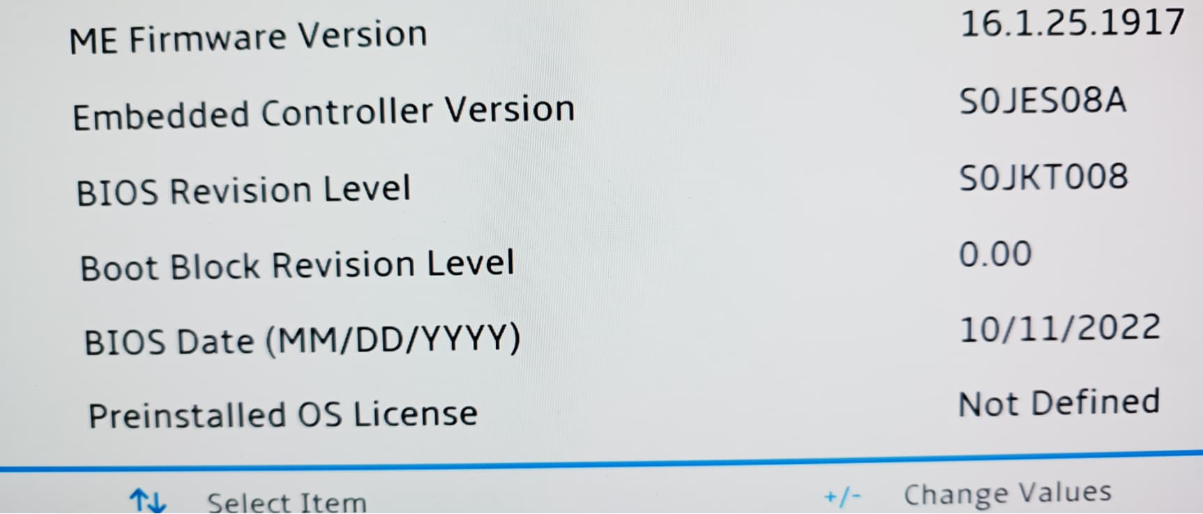
Here’s the ME version on this machine:
https://winraid.level1techs.com/uploads/default/original/3X/e/c/eca50ebfa549129e5f2992f4acfa925b72863b09.jpeg

So, when the correct BIOS for the correct board is flashed, there is no chance of bricking right? Of course, provided that the right commands/flags are used and the BIOS is proper. I’ve done it for my Z390 long long time ago and it was success. I had to downgrade the BIOS using the FPT using Los N BIOS guide i think :wink: Just scared as it bricks so many boards as per users on the internet.

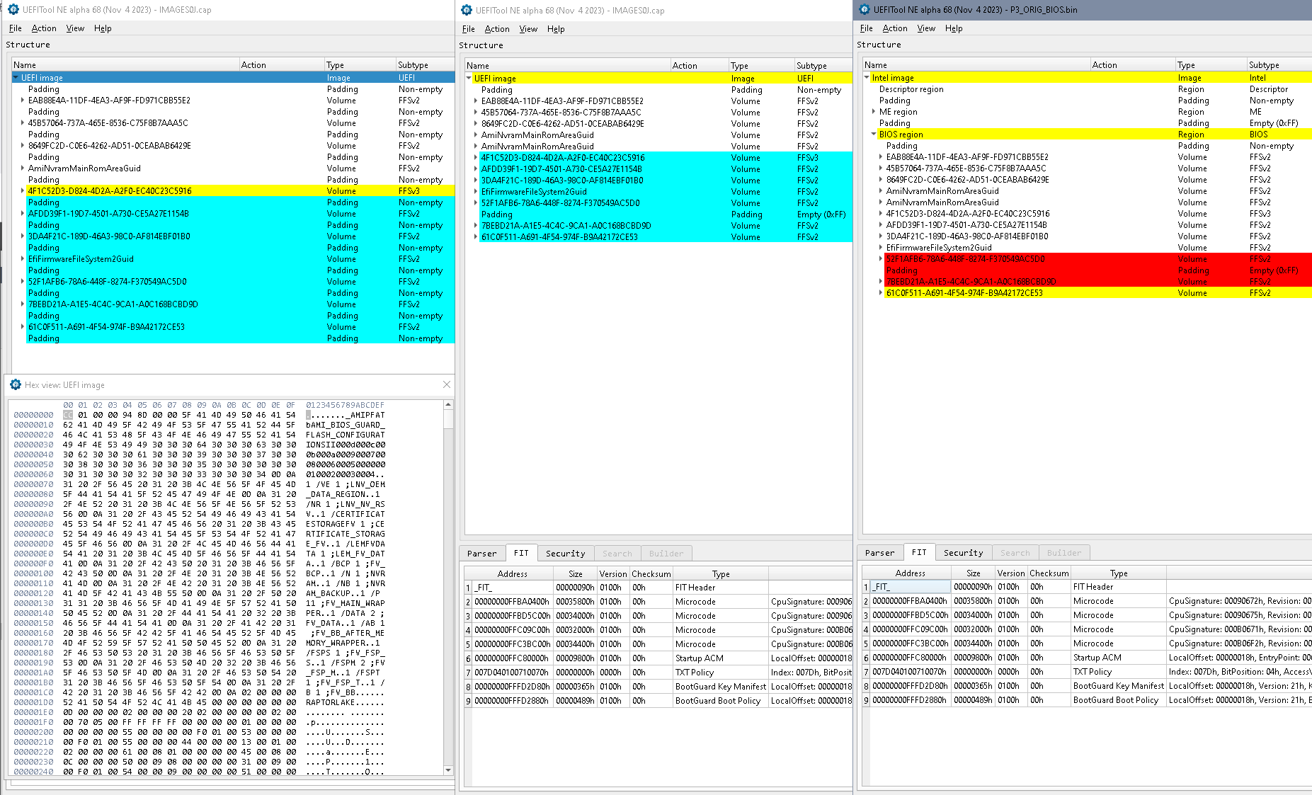
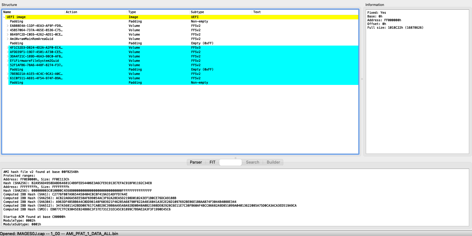
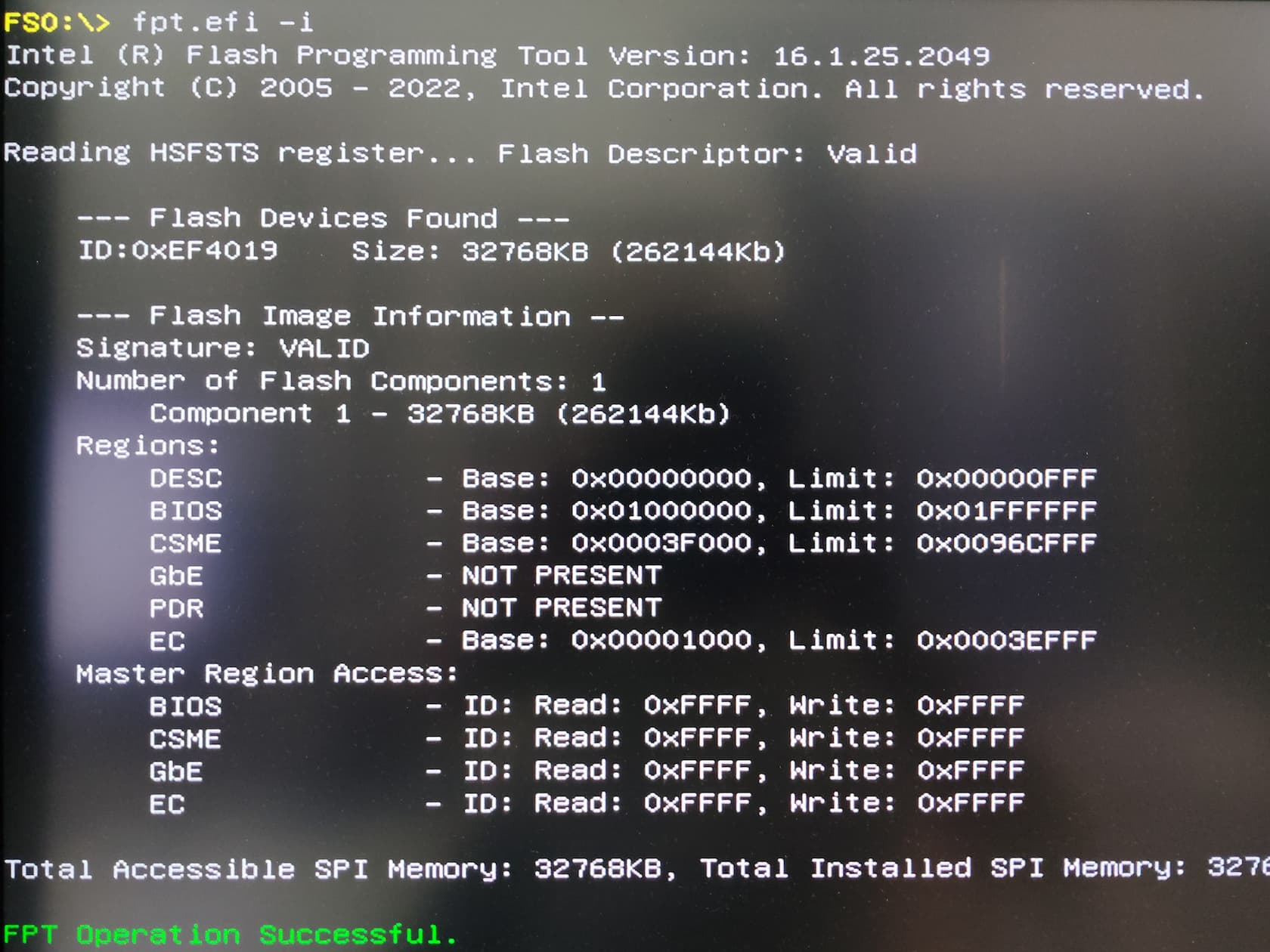
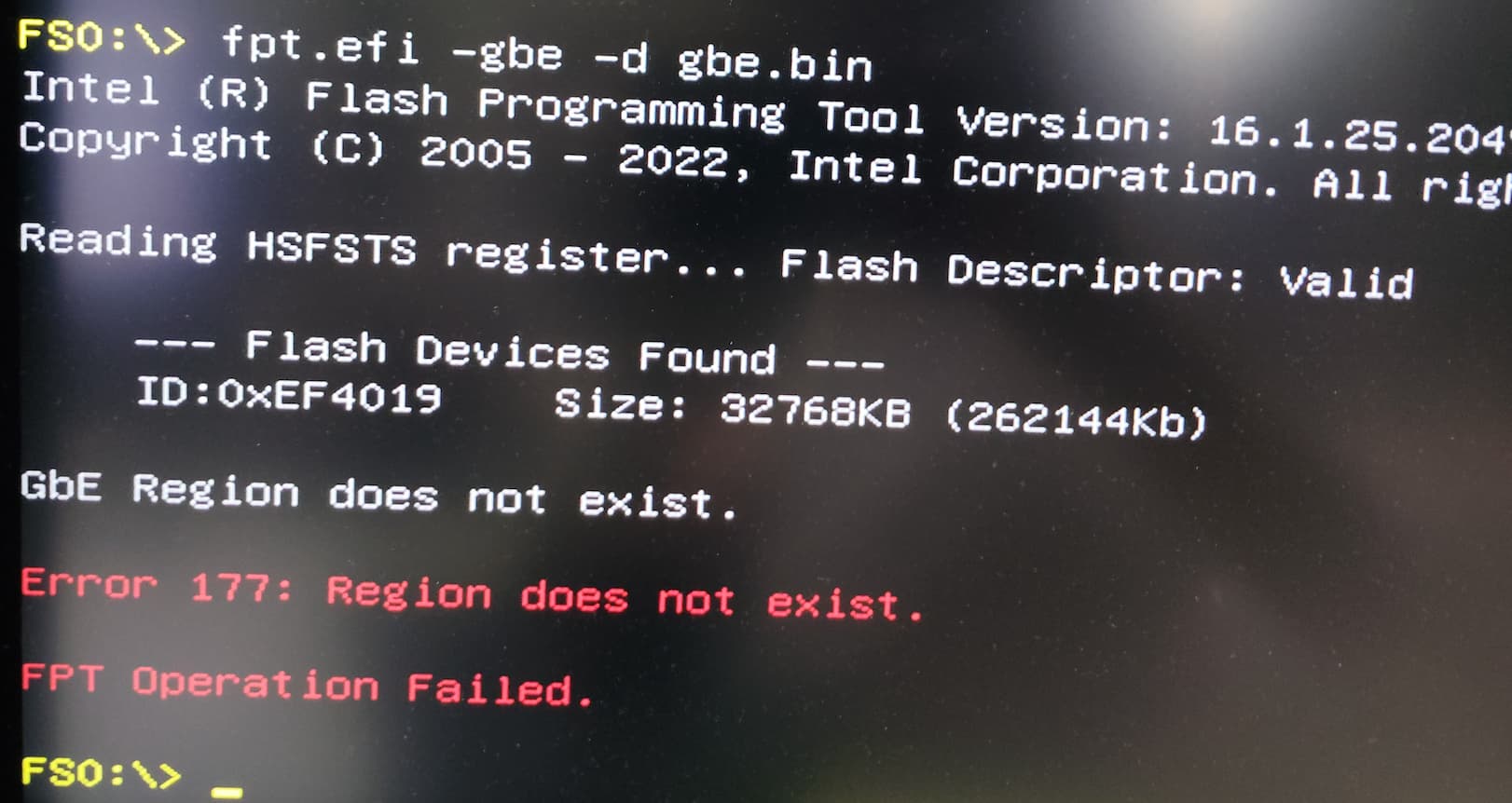
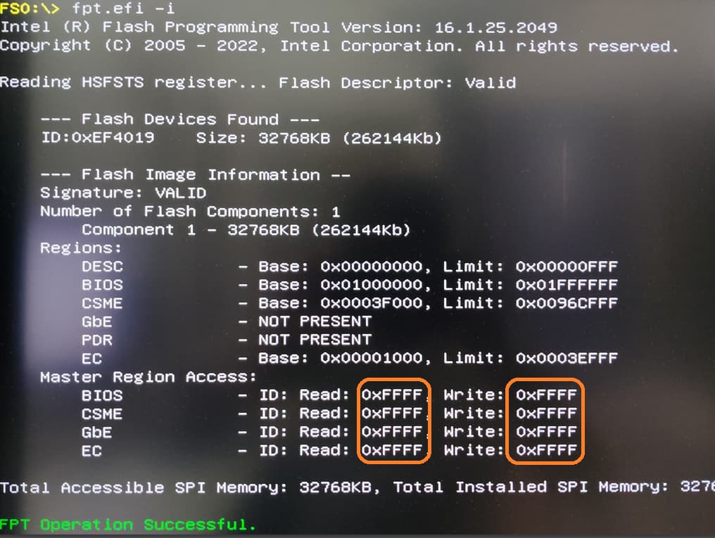
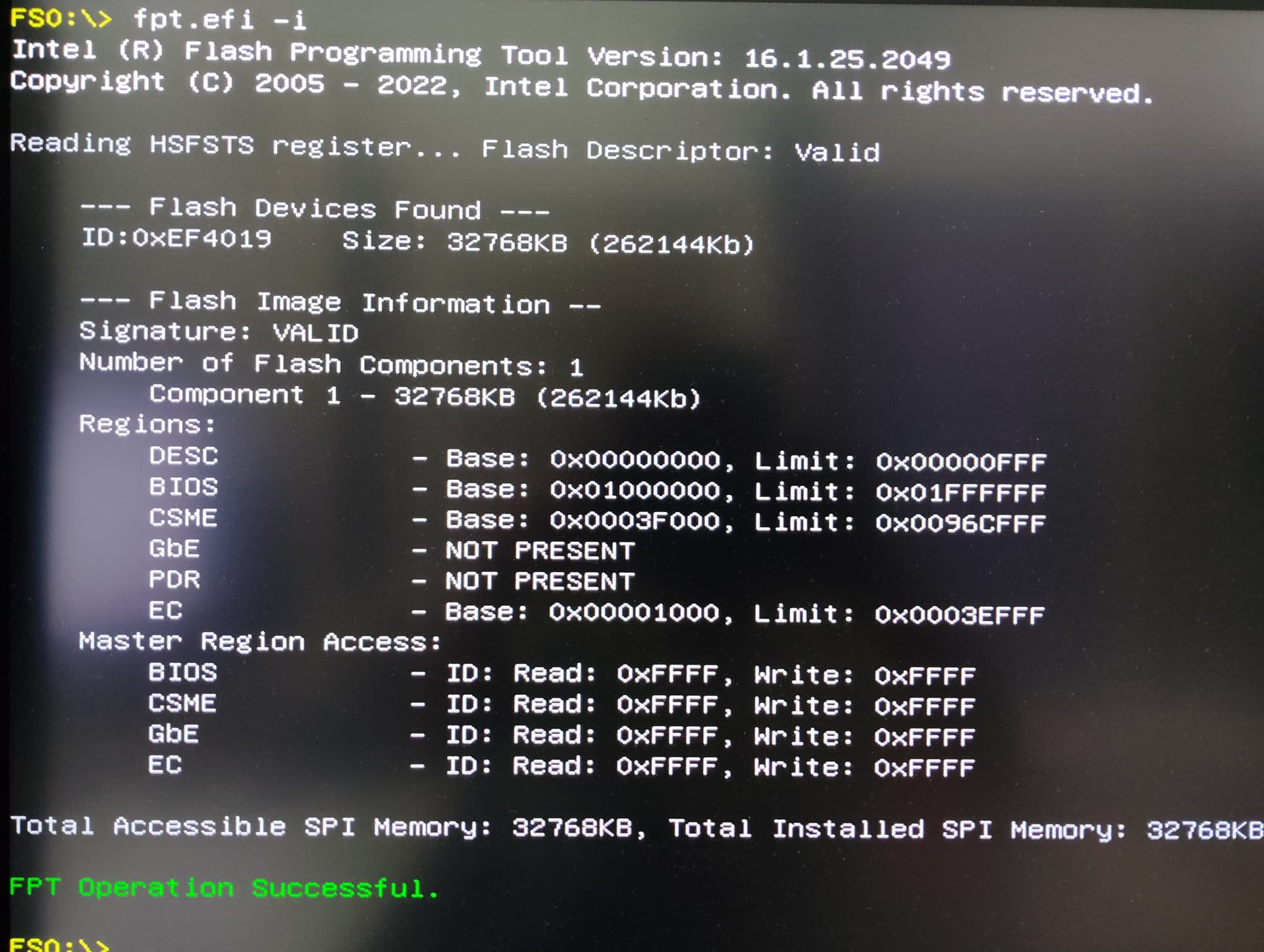
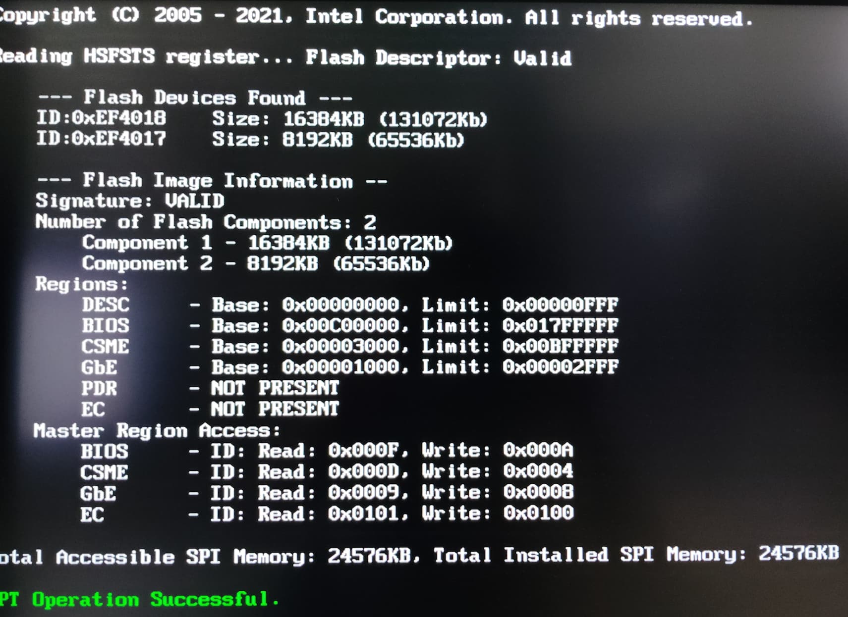
One thing i want to ask is, boards with Intel Ethernet chips, there is usually a Gbe region right? I cannot see it in the extracted file and neither when i was dumping, it says no Gbe region found. Maybe i used a wrong Fpt version. Very scared. If you have the right version of the Fpt, please link me here.

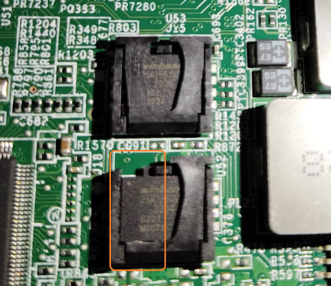
I’m not sure, if it will let me flash, but i hope it does. In the worst case scenario, i can use CH341A programmer right? To set the jumper in the service postition, it is usually ME_DIS right? As that’s one of the indication near the jumper!

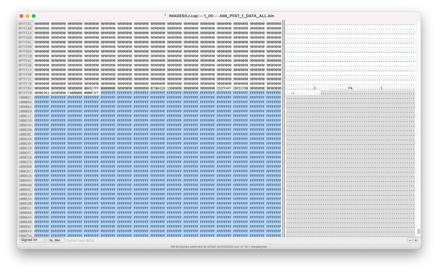
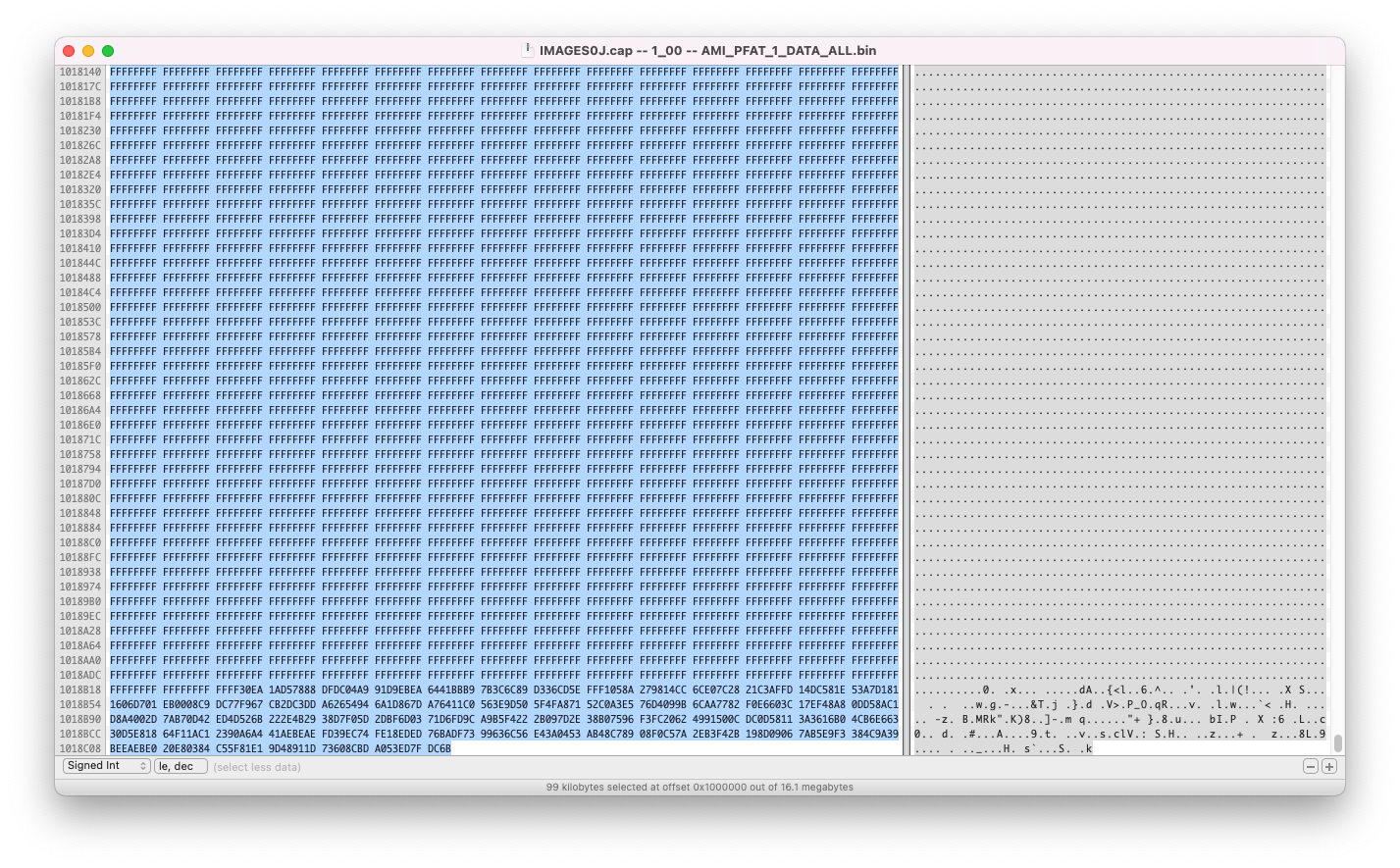
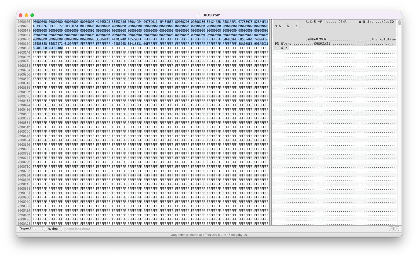
Lastly, why do i still have to cut the end of the file to exactly 0x1000000? Just curious. Is it because the dump from the machine has the same length?

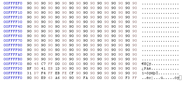
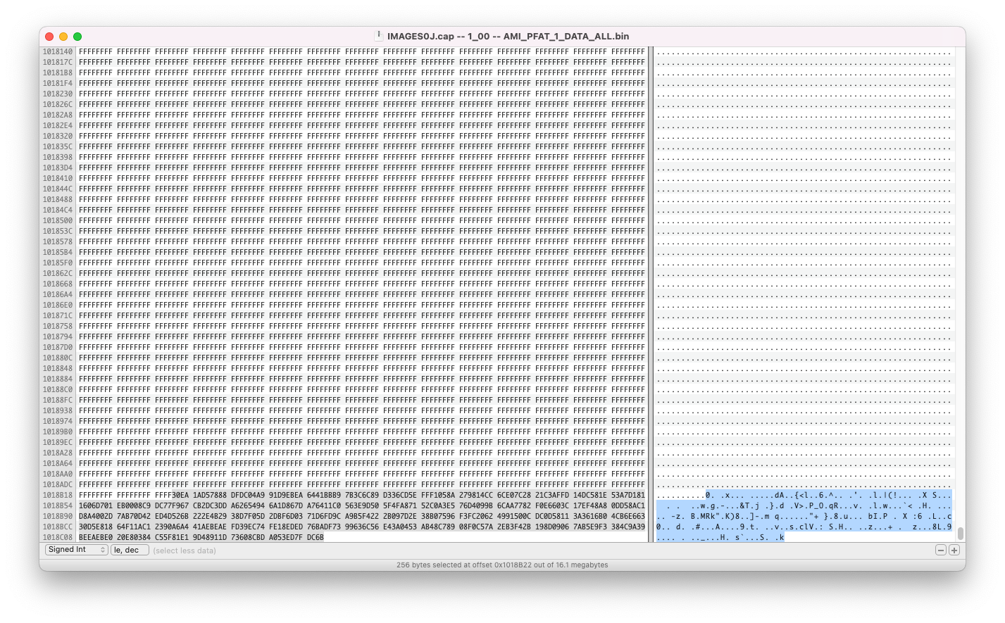
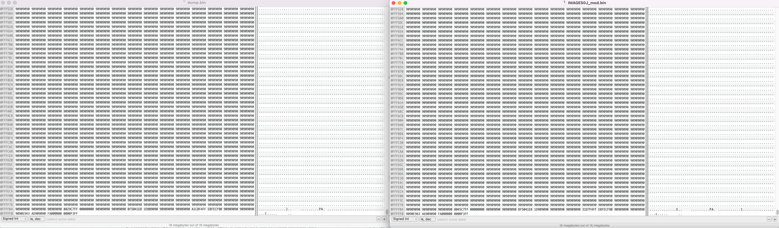
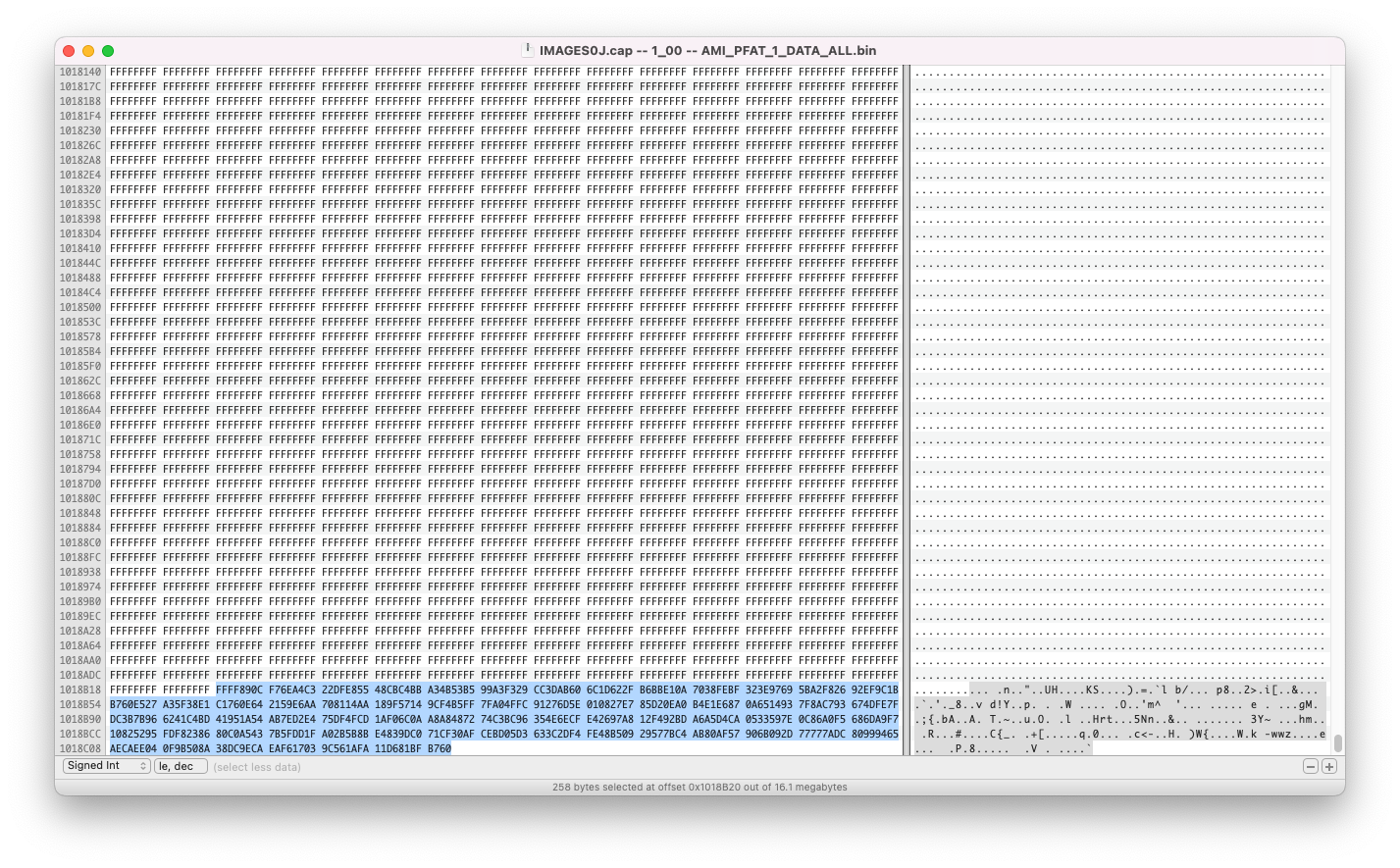
FFWhen i scrolled at the end, i saw these too? Are these not important at all?

Especially, this one, which is at the end:

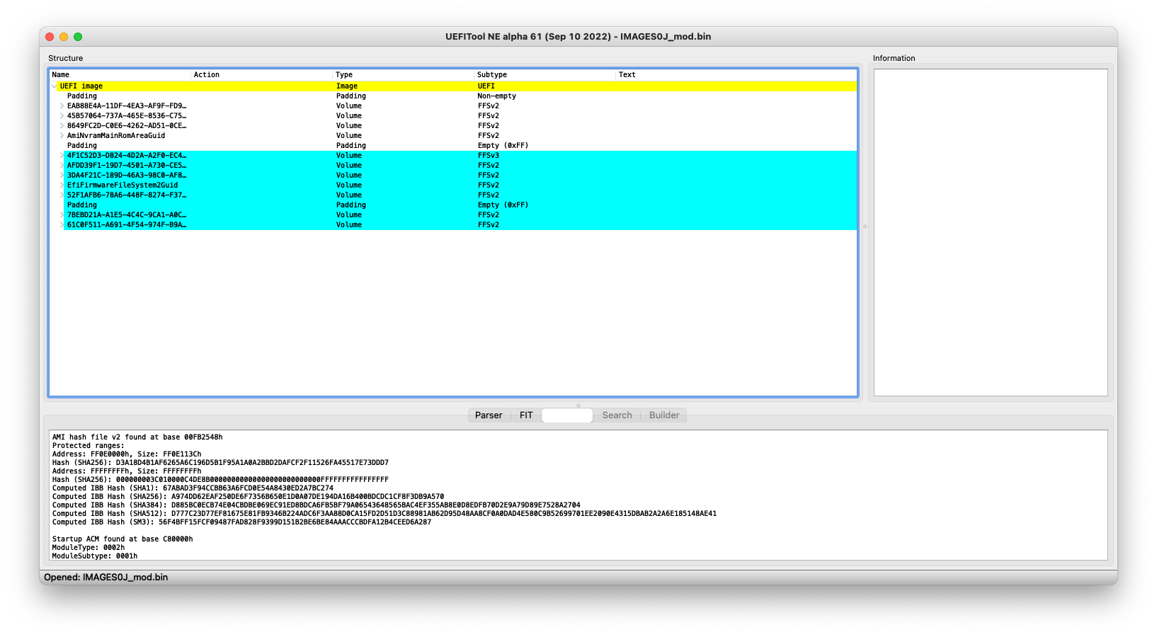
Also, i noticed that there are paddings at the beginning of the file. Is that OK?
And, can’t we flash the extracted file?

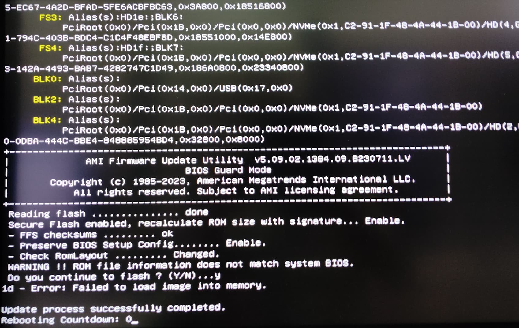
Do you think, i should flash one step down so that i can use the official tool to program everything correctly, just for a safe side? I mean maybe i cannot re-flash using the official tool as the BIOS will be the latest.

I think first i should clear CMOS, set the jumper to default, and dump BIOS region and also a full dump using the Fpt and then try to flash the extracted and modded file. What do you think friend?

Also, in the original dump i posted previously, it contains this piece of information but the extracted one does not. Would that be okay or i’ll have to add this to the extracted file?

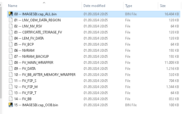
Also, after cutting to the length you mentioned, the BIOS is now 16.8 from 16.9. Would it be wrong if i flash the extracted BIOS, with no cut?

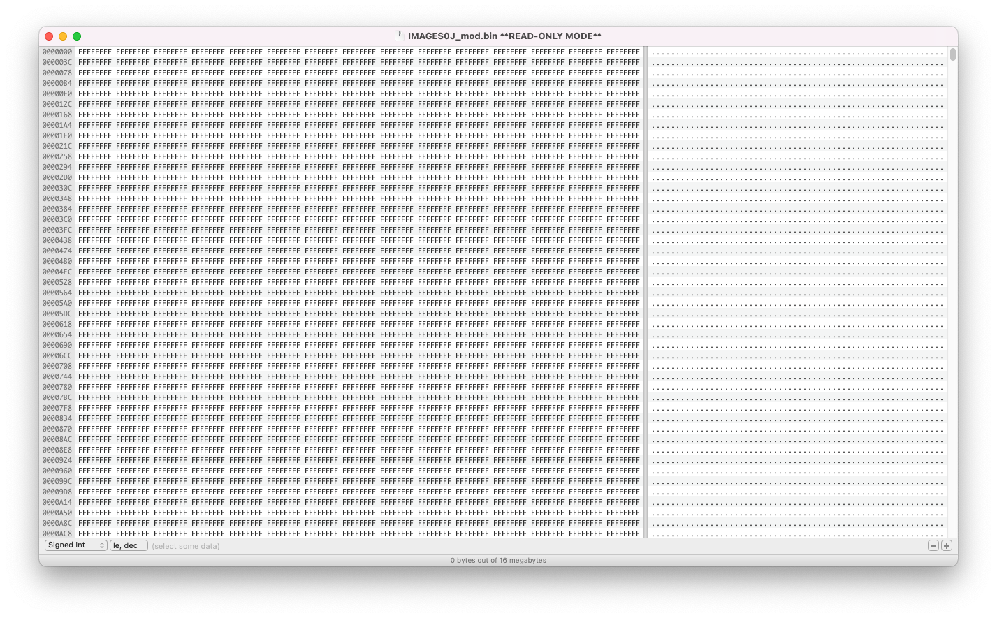
I used HEXFiend on Mac and made the cut in the extracted file but it saved like READ Only. I think the file has a permission issue and will be fixed using chmod but i don’t think it would be a problem when flashing with the FPT or something else.

Okay, there is a problem. The file i cut, i cannot open it with UEFITool. It says cannot read. Does this mean i made the cut wrong?

Also, i checked the size of both the BIOSes. The original .CAP and the extracted .bin files, both are 16.9MB. Does this mean i can go and flash the .bin (extracted) BIOS without cutting?

Would recommend not to flash anything at this point.

  • I don’t know what format the programs packed with the updates expect- there’s a high chance of bricking.

  • The file you created now doesn’t even have the correct format for use with fpt

But you mentioned i’m good to go in your previous post.

What do you mean? Are you talking about the extracted one or the file in which i made the cut?

Hello @lfb6 So, i started fresh with one step older BIOS and have done everything as per my knowledge. Please check and verify if the work is correct. Here is the link to the Files:

Also, i’ll explain what i did exactly, just to make sure we both are on the same page.

  1. The Machine jumper was in normal postition. I booted via FPT (EFI64): 16.1.25.2049 and made two dumps using the command:

fpt.efi -d spi.bin

  1. Then i checked the info and also flashed the BIOS region using the command:

fpt.efi -bios -d bios.bin

Both the operations were successful!

A weird thing i noticed that the FPT does not recognize the chip. Maybe i used incorrect FPT version?

Secondly, the FPT cannot find the GBE region. I’m not sure why. Maybe the GBE region is not the SPI but on the Ethernet chip itself, i’m not sure what i’m saying is even correct. Maybe the GBE region access is locked/protected. The system definitely has 2*Intel (1GbE) and (2.5GbE) chips on the board.

  1. Exited from FPT and shut down the system
  2. I downloaded s0jj313usa.zip from official Lenovo site.
  3. I used the extractor and extracted the BIOS from the guarded file i.e. IMAGES0J.cap and a new directory was created using the extractor automatically with the name IMAGES0J.cap_extracted.
  4. I copied IMAGES0J.cap – 1_00 – AMI_PFAT_1_DATA_ALL.bin to a new location and opened the file using HexFiend and compared with the original BIOS Region dump i.e bios.bin and IMAGES0J.cap – 1_00 – AMI_PFAT_1_DATA_ALL.bin and to make the size identical as the original FPT dump, i made the cut as per your instructions and then saved the changes to the same file. Then i copied it to a different location and saved it as IMAGES0J_mod.bin in a new directory (Cutted). You can find all these files and directories in the .zip file i uploaded above

The good news is that now the cutted file (IMAGES0J_mod.bin) can be read using UEFITool:

  1. I compared both the file side by side and it looks fine to me. Of course, the stock has bit changes.

Also, you mentioned that the Lenovo only updates/programs the BIOS region. Is it for all the Lenovo machines or just the P3 Ultra? And talking either of the situation, how is the entire EEPROM (all BIOS regions are overwritten i.e. Descriptor, GbE, ME and BIOS) on Lenovo Machines?

So, i’ll wait for your final confirmation and try to flash. First, i wish to try using the USB method (using Lenovo Tool) and if it fails, the FPT is the second way.

@lfb6 Can you confirm mate?

OK, the last cut file you linked- which opened fine in UEFIToolNE looks good (IMAGES0J_mod.bin in Cutted).

Your machine specific data are in padding of your original files

  • full image from 0x1000000 to 0x1020000
  • bios region 0x0 to 0x20000

You can just copy them over to IMAGES0J_mod.bin, replacing 0x0 to 0x20000

That’d be then a bios region for flashing with fpt- like (ftp.efi -bios -f IMAGES0J_mod.bin)

There’s no GbE region configured, its normally about 0x1000 to 0x2000 in size, here’s a completely different looking padding size 0x3E000 and it’s EC region, got its own Lenovo reference S0JES08A

What I wonder about:

How did run this command? Jumper in service position or in default position? If in service position could you do it again with jumper in default position?

If the read / write access table still shows FFF for all regions that means someone was here already, that’s not stock. In this case on should probably re- initialize the ME region, too.

Glad to hear. So, am i good to flash that file using FPT? BTW, i asked you which FPT version to use.

BTW, what do you say about the FPT not recognizing the chip model? Its always like WQ… but here it says 0xEF4019 ;(

What if i flash the BIOS region and then use AMIDMI to code those missing information?

Also, at the end of the original BIOS, i have these. Are those not important?

Yes, yes.

Are you sure about that? Cause, on my Z390 AORUS MASTER, the board had Intel Ethernet and there was GBE region and i actually backed up and used SAVEMAC flag to retain the MAC Address. Not sure why it is not configured on this machine when the board has 2*Intel NICs.

Also, how did you derived the reference to S0JES08A? I’m really curious :slight_smile:

As mentioned in the second last post, the jumper was on 2-4 (Default) and i used FPT (EFI64): 16.1.25.2049. Firstly, i used -H flag to check what flag the tool supports as i wanted to have as much information as possible. So, then i used -i flag to obtain the information of the SPI.

Jumper in default postition i.e 2-4. The board diagram states that PIN 1-3 is ME_DIS and 2-4 is Default and 5-6 is CLR_CMOS (FW).

I can take a full dump+BIOS region dump+get the information of the SPI in the service position. Just let me know!

Holy cow. Does it mean that FFF means Read and Write enabled for the SPI? Also, what do you mean by not stock? The BIOS on the machine is not the stock BIOS? Could be possible. Its from eBay.

Would the BIOS (Lenovo original), not contain ME region? If not, how can i flash the actual stock ME, which is meant for this machine? And how do i re-initialize the ME region after flashing the BIOS region?

What about the EC and other regions? Those needs to be programmed as well or what?

Lastly, you mentioned that the Lenovo only updates/programs the BIOS region. Is it for all the Lenovo machines or just the P3 Ultra? And talking either of the situation, how is the entire EEPROM (all BIOS regions are overwritten i.e. Descriptor, GbE, ME and BIOS) on Lenovo Machines?

@lfb6 Okay, so the machine was powered down and nothing was plugged for couple of hours and then, i changed the jumper position to 1-3 (ME_DIS) and then tried to get the information:

What one weird thing i noticed is, with the ME_DIS jumper, the fpt.efi is bit slow. With the default position, the fpt.efi was quite fast!

Let me know if you want the dumps with ME_DIS jumper.

Thank you for your all help!

@lfb6 Let me know if i can proceed with the FPT or any other method or is there anything i have to prepare, before flashing the modded BIOS. Also, should i flash using Default jumper or ME_DIS?

Okay, so tried to flash the IMAGES0J_mod.bin using the USB Method using the Official Lenovo BIOS tool and here is what the flash2.efi says:

So, as i guessed, it was the large file name and when i used the original file name, the flash2.efi, detects the file but with a warning:

What surprises me is that, now the same flash2.efi tool says that Secure Flash enabled and no such error like it used to give in the beginning. So, the change i.e. (no Secure Flash ROM Verify Fail 0x1) was due to the BIOS was not extracted or is it because we have made the cut after the extraction?

@lfb6 I’m awaiting on your confirmation to proceed with the flashing!

EDIT: So, @lfb6 i took the courage and went ahead to flash the modded file and i was quite positive that it would be a success but then, here is what is see when continuing flashing with official flash2.efi tool provided from Lenovo in the one step back BIOS package:

So, it seems like i’ll have to use the FPT to write the BIOS region. Let me know if i am good to go!

I’m not sure why it says failed to load image into memory. Do you have any clues friend?

EDIT: So, it seems like my machine is bricked. I flashed using the exact command you provided above and after the flash, i used fpt.efi -greset and then the machine restarted and then it shut down on its own. When i try to power it on, the light turns on, the fan spins for a moment and then it shuts down again. What the heck did just happen. What to do next now? Am i all dead?

EDIT: So, i tried to remove the power adaptor and also tried to Clear CMOS, used ME_DIS jumper but its a no go. I guess i will have to use an external programmer and hopefully, i can revive the machine as i have the full dump obtained via FPT. The following are the BIOS chips i guess. Thinking that one might be backup chip and one master and that as both the chips were not programmed, i removed the bottom one and tried to power on, same situation. When i tried to keep the bottom and remove the top one, the system does NOT even power on. I also tried to swap the chips in the correct orientation and still, its a no go. Really disappointed now. Everything was done correctly or i had to write a new ME as well? If that’s the case, i should be able to start the system with the ME_DIS jumper but it does not work!

@lfb6 PLEASE HELP!!!

The BIOS chip seems to be Winbond 25R256JVEN. Not sure which programmer to buy and write back the backup file i have dumped before.

(Never told you to use the AMI tools with this file, they’re quite unpredictable and if you didn’t try out them before on the very machine they might do what you want or not- and what kind of file they want with certain switches set isn’t documented.)

I’d been indeed the next question if you checked for a second bios chips- those machines are announced with boot block recovery / self healing bios - that normally requires a second chip which has to be programmed congruent to the first chip. Then changing just one chip will brick the machine since the information no longer is congruent.

That won’t be easy - especially since I can’t find any other P3 dumps.

Complete bios or bios region for updates- Lenovo has some gaming(?) machines where the bios update contains a complete dump, but most machines got their bios and ME updates separately.

Regarding the ‘all open’ flash descriptor- this is the output from my ME 14 desktop:

Master Region Access:
BIOS - ID: Read: 0x000F, Write: 0x000A
CSME - ID: Read: 0x000D, Write: 0x0004
GbE - ID: Read: 0x0009, Write: 0x0008
EC - ID: Read: 0x0101, Write: 0x0100

So if these are all set to FFF it’s suspect that someone was there and changed them already. So I think there could be a reason that the machine was sold on ebay?

You need to dump both chips with a programmer. Looks like socketed WSON, so you’d need to buy an adaptor in addition. Check for type if it’s 1.8V or 3V.

Yes, i’m aware of that. But if you check my previous post, AMI tools failed to flash and the machine was working fine until then. It got bricked when i flashed with the FPT. As the work was done and after your confirmation, i went ahead to flash, i still have the photo of the FPT when flashing. I used fpt.efi -bios -f BIOS.bin and the write was successful. Then i used fpt.efi -greset and the machine starts and shuts down itself after 2-5 seconds. I’m not sure whether the -greset caused the issue. But i don’t think so.

What i think is, maybe we had to write to the whole SPI regions or it got bricked as the machine has Dual BIOS (yes, it has two chips). Or could it be a reason that i used wrong version of FPT?

Yes, i think it has Dual BIOS as there are two BIOS chips.

I think this is what exactly happened. I think we needed to flash the main BIOS chip first and then the backup chip. But if there is Dual BIOS, after removing the other chip, with one of them, the system should still be bootable. That’s the concept of Dual BIOS, which acts as a backup. Isn’t it?

My friend can do that. Not a problem. He has the same machine :slight_smile:

Hmm.

I’ll check with my P330 Tiny and also the P3 Ultra my friend has!

So, i think you’re right. The below picture is from my P330 Tiny and it detects absolutely fine. Moreover, it detects two flash chips and also has a valid GbE region as well. So, what does exactly 0xFFFF means?

Could be possible!

Yes, that’s the next plan!

Can you provide me some eBay or Amazon link please? I’ve never programmed such chips using external one.

The datasheet says its 3V:
https://www.mouser.com/datasheet/2/949/W25R256JV_RevD_06162020-1879221.pdf

I think when the adaptor arrives, i’ll first try to take dumps of the original chips from the bricked machine and then also try to flash the SPI dump i took on both the chips using FPT and check if the machines revives. If not, i’ll simply read the other machine using external programmer and flash those files onto the respective chips and hopefully, then the machine should revive as no experiment was done except for flashing the cutted file (which you verified) using FPT.

Do you think the complete dump i took using FPT.efi can be flashed onto the BIOS chip? Or i’ll have to take the dumps of both the chips from the other machine and then flash it?

No, this just makes the machine reboot and start cold from ME.

No Dual bios, that’d be easy. The contens of the two chips aren’t (probably) identical! I checked some examples from HP, there was parts of bios region and ‘other stuff’ locked like a corrupted version of the first chip.

Again- this isn’t dual bios, this is (most probably) another solution here!

A dump of these two chips in untouched / stock version would be great! Is the P3 of your friend from the same source as yours?

In this case (P330) the complete Intel image is divided onto two chips, the second chip has no redundant information!
FFF means all read and write allowed according to flash descriptor security

I’ll have a look later.

1 - you can flash the dump you made back to the chip which has the got the stock bios region via fpt.
2 - It’s possibly no longer possible to simply transfer firmware of a working machine. There’s still a TPM which has control data.
So please be careful, take dump of both the chips and lets check both dumps.
For you friends P3 one chip can be dumped by fpt, the other needs to be dumped (very carefully) with hardware programmer.

You need to be careful with these sockets, it seems these little covers are what keeps the chips down and pressed onto the contact- and seems to be the only thing. The missing part on the one socket- was that you or did you buy it that way?

Hmm

Yes, i think that too. Yesterday, i was reading at forum and found that on one of the Desktop, the main chip had everything and the other chip had DMI data.

Are you sure the P3 Ultra doesn’t have Dual BIOS?

Yes, i’ll get it tomorrow. I’ll get two types. One via FPT and the other one via the external programmer. I think it would be better to get with external programmer. I’ve been asking so many times, can you please mention the correct version of the FPT to use with this machine? And also, please link me with the adaptor for the external programmer

Sadly, no. He has the model with no dGPU variant. Plus, his BIOS is latest and has different ME. Would there be any problem? I think getting a dump with the external programmer of both the chips and then writing it onto my chips would revive the machine, hopefully. What do you think? Then, i’ll enable BIOS rollback and flash using official Lenovo Tool again to ensure everything is stock unmodified!

Hmm. I see

And how does that exactly happen? And will flashing the stock BIOS will reverse the FFFF into its original access?

Thank you!

The BIOS region only or the full dump i made? And on which chip i need to flash? As the machine is bricked, i need to use the external programmer to flash

Would that still work when flashing using the external programmer? Cause i can no longer use FPT as the machine is bricked. And when i use the external programmer, how can i only flash the BIOS region, leaving the rest default/untouched?

But once the machine turns on, the TPM can be cleared. Isn’t it? Or will it not let it even boot?

Yes, i will do that!

Really? Why is that so?

Why the mine P3 shows only one flash chip, when it has 2 in actual?

Yes, makes sense. I can confirm that the chip is in contact 100%. As i was new to this, the cover/lock got broken while opening the lock/cover. Are there replacement of the lock/cover?

Also, i don’t understand what caused the machine to brick when i flashed the BIOS region only. Not sure what went wrong ;(