Hi all im hoping someone here can help me enable Memory overclocking/Performance overclocking on my ASUS ROG G17 G712LW gaming laptop, im currently using the latest BIOS G712LWAS310.zip
i would be eternally greatful and also willing to pay for the priviledge
@evofq360 - Hey! Do you have flash programmer, such as CH341A or other? If yes, what is BIOS chip ID and send me a dump if you already know what software/version is compatible with that chip ID
If you do not have, then do below >> Also, please run the following command from the MEINFO / Win32 folder, and show me the bottom of the report >> MEINFOWin.exe -verbose
If you have already modified the BIOS in ANY way, you will need to re-flash it back to factory defaults using factory method (NOT FPT)!!!
Additionally, please remove all BIOS passwords, disable secure boot, and disable TPM or Encryption if you have enabled. Do this before moving on to below
If you do not have Intel ME drivers installed, install them now from your system driver download page, then start over here after reboot.
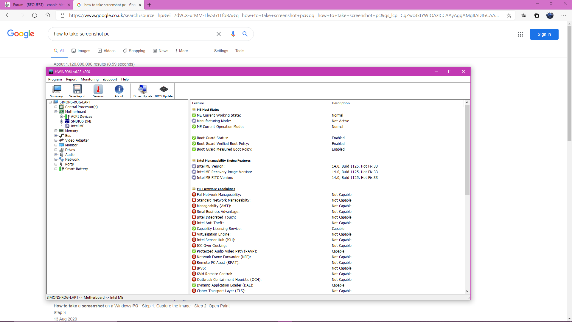
Check your BIOS’ main page and see if ME FW version is shown. If not then > DOWNLOAD HWINFO64 HERE <
Once HWINFO is open, look at the large window on the left side, expand motherboard, and find the ME area.
Inside that section is the ME Firmware version. Take note of the version. (ie. write it down or get a screenshot)
Once you have that, go to the thread linked below, and in the section “C.2” find and download the matching ME System Tools Package for your system.
(ie if ME FW version = 10.x get V10 package, if 9.0-9.1 get V9.1 package, if 9.5 or above get V9.5 package etc)
> DOWNLOAD " ME System Tools " packages HERE <
Once downloaded, inside you will find Flash Programming Tool folder, and then inside that a Windows or Win/Win32 folder (NOT x64).
Highlight that Win/Win32 folder, then hold shift and press right click. Choose “open command window here” (Not power shell! >> * See Registry file below *).
If you get an error, reply to this post with a screenshot of it, OR write down the EXACT command entered and the EXACT error given.
((If “open command window here” does not appear, look for the “Simple Registry Edit” below…))
Step #1
Now you should be at the command prompt.
You are going to BACKUP the factory un-modified firmware, so type the following command:
Command: " FPTw.exe -bios -d biosreg.bin "
>> Attach the saved "biosreg.bin ", placed into a compressed ZIP/RAR file, to your next post!!! <<
Step #2
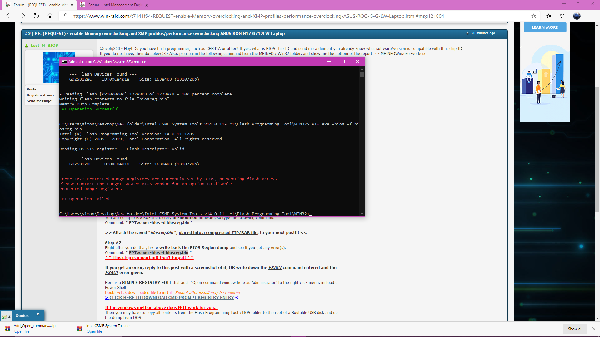
Right after you do that, try to write back the BIOS Region dump and see if you get any error(s).
Command: " FPTw.exe -bios -f biosreg.bin "
^^ This step is important! Don’t forget! ^^
If you get an error, reply to this post with a screenshot of it, OR write down the EXACT command entered and the EXACT error given.
Here is a SIMPLE REGISTRY EDIT that adds “Open command window here as Administrator” to the right click menu, instead of Power Shell
Double-click downloaded file to install. Reboot after install may be required
> CLICK HERE TO DOWNLOAD CMD PROMPT REGISTRY ENTRY <
If the windows method above does NOT work for you…
Then you may have to copy all contents from the Flash Programming Tool \ DOS folder to the root of a Bootable USB disk and do the dump from DOS
( DOS command: " FPT.exe -bios -d biosreg.bin " )
Additionally, please remove all BIOS passwords, disable secure boot, and disable TPM or Encryption if you have enabled. Do this before moving on to below
If you do not have Intel ME drivers installed, install them now from your system driver download page, then start over here after reboot.
Check your BIOS’ main page and see if ME FW version is shown. If not then > DOWNLOAD HWINFO64 HERE <
Once HWINFO is open, look at the large window on the left side, expand motherboard, and find the ME area.
Inside that section is the ME Firmware version. Take note of the version. (ie. write it down or get a screenshot)
Once you have that, go to the thread linked below, and in the section “C.2” find and download the matching ME System Tools Package for your system.
(ie if ME FW version = 10.x get V10 package, if 9.0-9.1 get V9.1 package, if 9.5 or above get V9.5 package etc)
> DOWNLOAD " ME System Tools " packages HERE <
Once downloaded, inside you will find Flash Programming Tool folder, and then inside that a Windows or Win/Win32 folder (NOT x64).
Highlight that Win/Win32 folder, then hold shift and press right click. Choose “open command window here” (Not power shell! >> * See Registry file below *).
If you get an error, reply to this post with a screenshot of it, OR write down the EXACT command entered and the EXACT error given.
((If “open command window here” does not appear, look for the “Simple Registry Edit” below…))
Step #1
Now you should be at the command prompt.
You are going to BACKUP the factory un-modified firmware, so type the following command:
Command: " FPTw.exe -bios -d biosreg.bin "
>> Attach the saved "biosreg.bin ", placed into a compressed ZIP/RAR file, to your next post!!! <<
Step #2
Right after you do that, try to write back the BIOS Region dump and see if you get any error(s).
Command: " FPTw.exe -bios -f biosreg.bin "
^^ This step is important! Don’t forget! ^^
If you get an error, reply to this post with a screenshot of it, OR write down the EXACT command entered and the EXACT error given.
Here is a SIMPLE REGISTRY EDIT that adds “Open command window here as Administrator” to the right click menu, instead of Power Shell
Double-click downloaded file to install. Reboot after install may be required
> CLICK HERE TO DOWNLOAD CMD PROMPT REGISTRY ENTRY <
If the windows method above does NOT work for you…
Then you may have to copy all contents from the Flash Programming Tool \ DOS folder to the root of a Bootable USB disk and do the dump from DOS
( DOS command: " FPT.exe -bios -d biosreg.bin " )
hi i dont have a programmer but i have done as you requested and enclosed intel ME pic also error message when trying to flash back bios, i cant attach biois even when zipped its over 6mb and it wont allow to attach so ive provided a link for you
https://www.dropbox.com/s/b4mogr72vdw8px…20pics.rar?dl=0
really appreciate your help
@evofq360 - Thanks! Missing this >> please run the following command from the MEINFO / Win32 folder, and show me the bottom of the report >> MEINFOWin.exe -verbose
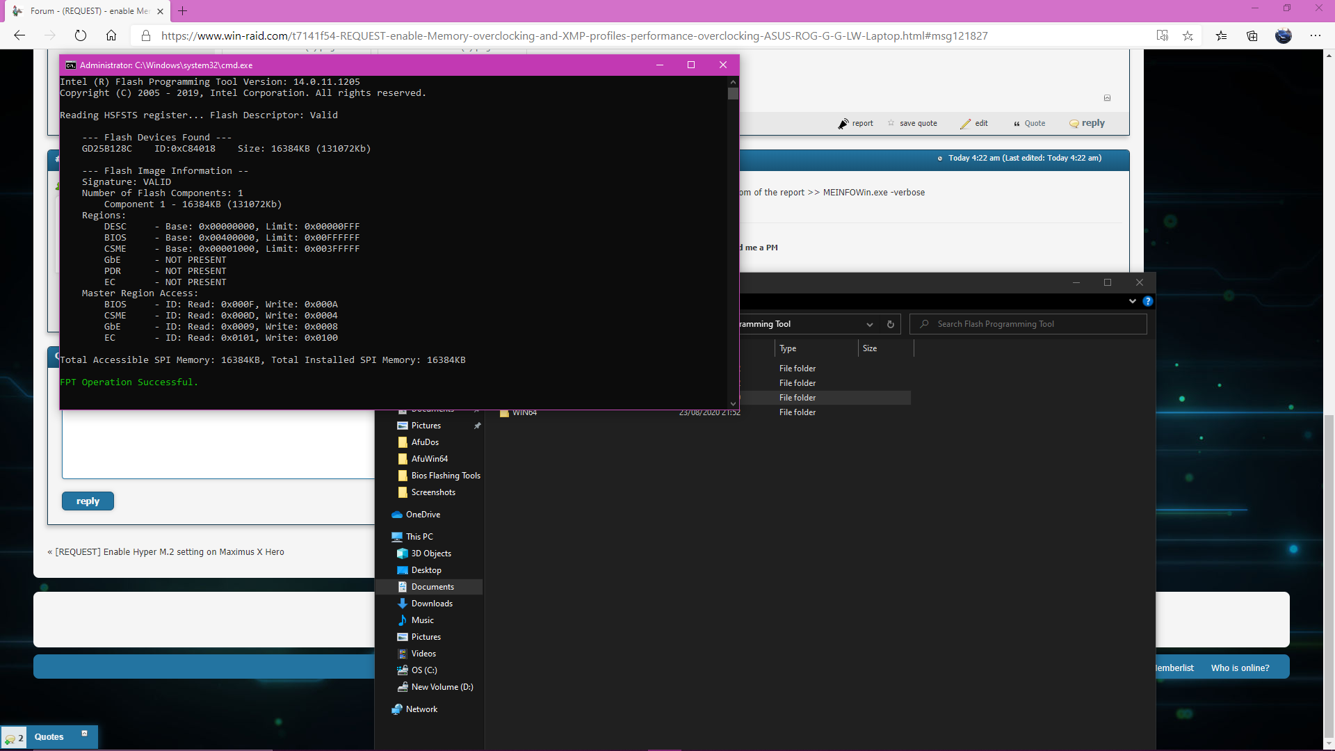
Please also, include image of this command run from FPTw.exe folder >> FPTw.exe -i
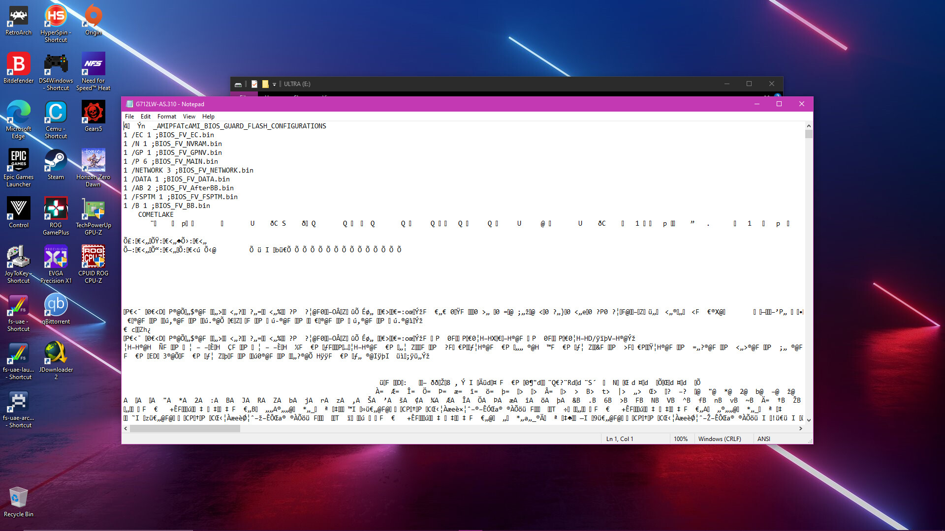
thanks for the reply here are the pictures of the commands you require
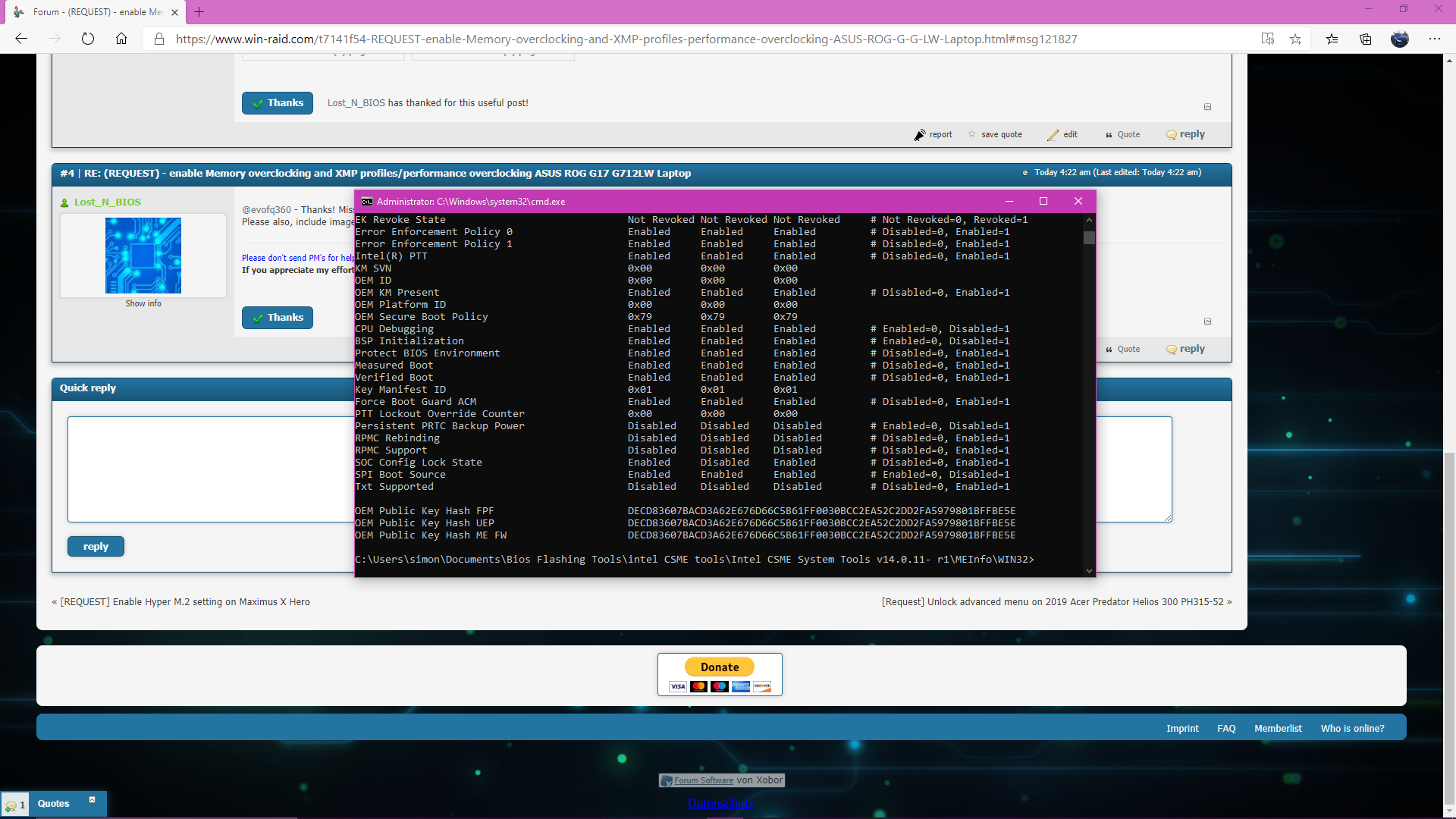
@evofq360 - Thanks. Sorry, but due to Intel Boot Guard, we can’t edit menu  See bottom of image #4 above, left/FPF Side, measured and verified boot enabled, this means we cannot do a menu mod edit on this BIOS, it will = brick
The only thing we can do is change any setting you want in place via RU, grub/setup_var, or FPT flash of NVRAM region only (Ideally, the first two are better, but FPT may be easier for you depending on how comfortable you are doing more technically involved things)
Here is a txt file of all settings we can change (hidden and visible in your BIOS) Scroll or search through, and make a list of what exact by name settings you want to change, and what you want them changed to, and I will give you directions on how to make the changes.
http://s000.tinyupload.com/index.php?fil…164862087665897
ok no problem, i really only wanted the ability to change ram settings/xmp profile as its not reading them correctly, its running at 2936mhz instead of 3200 timings are incorrect
really appreciate you taking the time to help
@evofq360 - All that can be set easily how I mentioned. Do you want me to gather the details for what all you need to change, and show you how?
If yes, please send me HWINFO64 report of memory section only, so I can see the XMP profile timings. (Report >> Create >> Txt, select only memory >> done)
Or, if you want, we can just first try enable XMP by itself and see if everything gets set properly?
To do that, is one command, either in grub using setup_var or you boot to DOS and make a change using RU program method.
I can give you the info, and link you to guided method to do it either way, just let me know.
You’re welcome, sorry this system has Boot Guard
Key is burned into the PCH, so you can only disable boot guard by replacing the PCH 
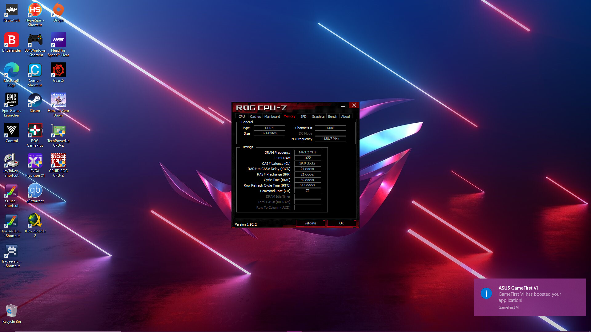
here is the hwinfo report also pic of timings
if you could help me set this up it would be great
on a side note when looking around bios and secure boot i saw i could export details of all the certs not sure if any of this is relevant, example pic below
report.rar (898 KB)
We can try XMP first, but that may fail and you may not be able to clear CMOS or reflash BIOS (ie soft-brick)
Maybe best you get flash programmer first, you need CH341A + SCOI8 / SOP8 test clip with cable
No, what you show in image does not matter to any of this. We can try XMP first, but that may fail and you may not be able to clear CMOS or reflash BIOS to reset it (ie soft-brick).
Usually when this happens BIOS will auto-reset to fail-safe, and let you into BIOS (ie failed overclock, defaults loaded etc), but this does not always happen when trying to OC memory or CPU voltages etc
Maybe best you get flash programmer first, you need CH341A + SCOI8 / SOP8 test clip with cable. If you want to go ahead and try XMP anyway, let me know.
Ahh, I checked your XMP profiles, those both look OK/Safe and should run, so you probably will not run into issue I mentioned above.
XMP is applied right now, just XMP1 instead of XMP2, at least I think this is what is set now. Well, at least it’s set to same speed as one of the XMP’s, I checked NVRAM and the actual setting is set to “Default Profile” and not XMP
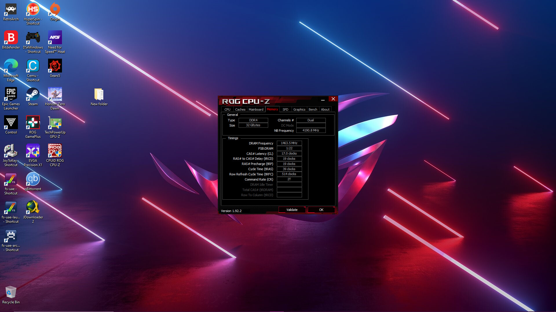
Please show me image of CPU-z memory tab, thanks
hi here is the cpu z files, thanks i agree i think its using xmp 1 profile
cpuz.rar (4.4 MB)
@evofq360 - Sorry, not sure what above file is, but looks like not something I need as it’s 4MB (I am on limited internet, so did not download)
I need to see screenshot of CPU-z with memory tab selected, that’s all. It’s using “Default Profile” which may be same as one of the XMP speeds, but I don’t think XMP profile is being applied because it’s not set that way and you say timings are not correct
sorry i was half asleep when i did last reply, here is cpu-z screenshots
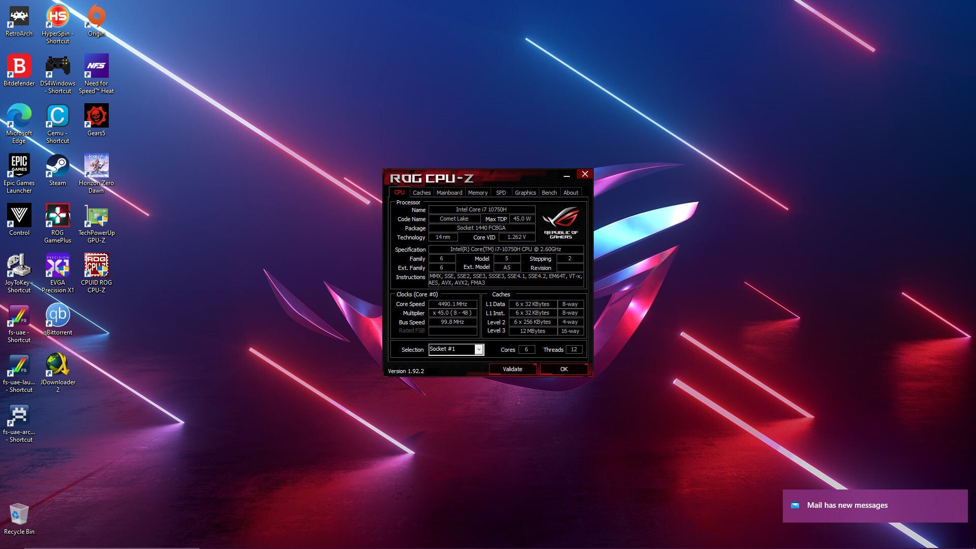

Thanks! Yes, so XMP is not being used, but default/auto speed is the same as the lower speed XMP
Here is how to enable XMP1 or XMP2 - using RU method - Go to section 2.2 and make bootable USB with RU program, then read 2.3-2.5
http://forum.notebookreview.com/threads/…-issues.812372/
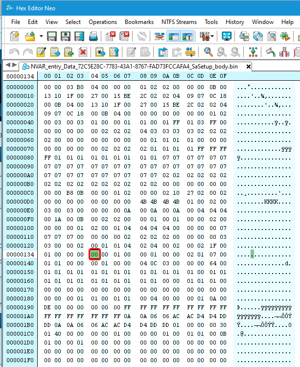
You will be making change in SaSetup, NOT Setup as the guide above mentions, SaSetup is in this GUID >> 72C5E28C-7783-43A1-8767-FAD73FCCAFA4
You will be changing the variable at 0x134 from 00 to 02 for XMP1 or 03 for XMP2. If you are not familiar with how hex works, go down to line 0130, then go out to the 5th digit on line 130, this = 134
Below is an image example of the exact area you will be editing with 134 highlighted, so the data you see in there will all look same as below (this is not RU image, it’s a hex editor)
do i need to unlock bios first aas is mentioned in setup 2.5 or just edit the sasetup above and save?
------------------------------------
I edited the exact hex as requested. Saved it and it shows as successful update but cpuz still shows the same.
I went back in to hex and confirmed the hex was saved correctly. I tied using xmp 1 and 2 but no change in cpu-z
Sorry for not mentioning! No, you do not need to do anything that guide is talking about, other than use it to learn how to use and work with RU program
That guide is meant for another purpose (bypassing locks that block flashing in mod BIOS), we only use it so you know how RU works, to then directly make the change I outlined above 
* Edit - So, no change in CPU-z memory tab, at all? Show me image of CPU-z Memory tab, with XMP1 or XMP2 set
We may have to set it all manually instead, which is not a big issue, but you’ll have to make a lot more edits at once.
I will help you and outline all the info for this tomorrow when I get back in and have more time  Meantime, please wait, so you don’t break anything
no no change at all im afraid, i will wait, thanks again
OK, thanks! It may be this >> First try, change this!
OverClocking Feature, VarStoreInfo (VarOffset/VarName): 0x1B7 >> Change 00 to >> 01 to enable Overclocking Feature
^^ This is in “CPUSetup” >> B08F97FF-E6E8-4193-A997-5E9E9B0ADB32
Then test that as-is, only change, with XMP1 or XMP2 again. If no change, OK, still leave it at 01/enabled, then below move onto setting up memory manually later when I have time to finish out all the info for you
@evofq360 - Never mind above! I see XMP changes applied in the image you attached above! Timings are now changed to XMPO profile #1 >> 17-19-19 there, vs 19-21-21-21 before!
So maybe just max speed of your chipset is limited to 2933
I will still write out all info I was in middle of, so you can adjust everything manually
really appreciate it,
thanks
@evofq360 - You’re welcome!
If you want to confirm these changes are being applied before trying to overclock or make actual changes, enter the values selected in blue below, these are current/stock in-use settings and or one less (IE one lower timing, or one memory speed lower etc)
Just so you can see changes happen, before you try to apply what you want. But, as I pointed out above, as soon as you enabled XMP the timings changed to correct values, just speed was limited to it’s current max, either by CPU or chipset.
So you’ll have to use that as Max speed and tighten timings, or lower speeds and tighten timings even more, or it may be possible that one of the combos below (100x something or 133 x something) will get you to 3000 or 3200
Memory profile, VarStoreInfo (VarOffset/VarName): 0x134 << Set 01 = Custom
QCLK Odd Ratio, VarStoreInfo (VarOffset/VarName): 0x0F << Set 01 Enabled
Memory Reference Clock, VarStoreInfo (VarOffset/VarName): 0x0C << Set/leave 133 (00) default, or can set 100 (01) This is what you are multiplying the memory timer against
Memory Ratio, VarStoreInfo (VarOffset/VarName): 0x0E << Set based on one of these scenarios below, using variable hex values in hex in (xx)'s
If memory reference clock set to 100 then following = memory speeds after memory ref clock x memory ratio
100 x 26 (1A) = 2600
100 x 27 (1B) = 2700
100 x 28 (1C) = 2800
100 x 29 (1D) = 2900
100 x 30 (1E) = 3000
100 x 31 (1F) = 3100 This is max for 100 memory ref clock, due to max memory ratio = x31
133 x 20 (14) = 2666
133 x 21 (15) = 2800 (2793 actual)
133 x 22 (16) = 2926 - This is what is currently being applied value by stock/default, see the 1:22 FSB:DRAM in CPU-z memory tab, that is this. So you can set this manually and speed will remain as it is now
133 x 23 (17) = 3059
133 x 24 (18) = 3200 (3192 actual)
tCL, VarStoreInfo (VarOffset/VarName): 0x10 << CAS Latency (First timing) >> to set this to actual 17 you apply >> (11) and so on >> 14 (0E), 15 (0F), 16 (10), 17 (11), 18 (12), 19 (13), 20 (14), 21 (15), 22 (16), 23 (17), 24 (18) (MAX)
tRCD/tRP, VarStoreInfo (VarOffset/VarName): 0x16 << Second and third main timing, they are combined only in this BIOS, you can’t set separately. Same as above ^^ (MAX = 63 (3F), see below for many values) >> Stock/auto value was 21 (15)
tRAS, VarStoreInfo (VarOffset/VarName): 0x14 << 35 (23), 36 (24), 37 (25), 38 (26), 39 (27), 40 (28), 41 (29), 42 (30), 42 (2A), 43 (2B), 44 (2C), 45 (2D), 46 (2E), 47 (2F), 48 (30), 49 (31), 50 (32), 51 (33), 52 (34), 53 (35), 54 (36), 55 (37), 56 (38), 57 (39), 58 (3A), 59 (3B), 60 (3C), 61 (3D), 62 (3E), 63 (3F), 64 (40), 65 (41), 66 (42), 67 (43), 68 (44), 69 (45), 70 (46), 71 (47), 72 (48), 73 (49), 74, (4A), 75 (4B) 76 (4C), 77 (4D), 78 (4E), 79 (4F), 80 (50), 81 (51), 82 (52), 83 (53), 84 (54), 85 (55), 86 (56), 87 (57), 88 (58), 89 (59), 90 (5A) >> Max = 90 (5A)
tCWL, VarStoreInfo (VarOffset/VarName): 0x11 34 (22) MAX
tRFC, VarStoreInfo (VarOffset/VarName): 0x19 1023 (3FF) MAX - Stock/Auto value was 514 (202) << This would go into 16-bit hex as Little Endian (backwards) and would occupy two byte spaces 0x19 and 0x1A. So 02 02 = 202, or more accurately = 0202 - This is set by default to this value, so you should see 02 02 at 0x19-0x1A
Memory Voltage, VarStoreInfo (VarOffset/VarName): 0x3 << Default 1.20V (B0 04) >> 1.10V (4C 04), 1.20V (B0 04), 1.25V (E2 04), 1.30V (14 05), 1.35V (46 05), 1.40V (78 05), 1.45V (AA 05), 1.50V (DC 05), 1.55V (0E 06), 1.60V (40 06), 1.65V (72 06)
Major Important thing to keep in mind here, ALL values are in HEX
You can use windows calculator in programmer mode to see what hex value is for any decimal value.
Select the decimal option and enter value, then up top you will see the decimal value you enter but above that you’ll also see it’s hex equivalent.