@ALviK98 : the GR8 cooler is really small and possibly designed for a TDP of 65W. while the G20CB/G20CI cooler has its origin from G20AJ (I7 4790) and can handle a TDP of 84W and works fine with a TDP of 95W (i7 9900k) and liquid metal resulting in 65°C max. cpu core temp on 95W (8cores full load).
you should consider using liquid metal (conductonaut) as thermal compound between cooler and cpu. But since 9600kf has a TDP of 95W it may fail and get way to hot. 9700f has a TDP of 65W and may work considering temperatures.
------------------------
@ALviK98 : Yes, the G20CB had a fully populated 3(CPU)+2(iGPU) phase VRM.
For such hardware hacks I have access to a fully equipped rework station like this ones https://paceworldwide.com/product-catalog/bga-rework-systems
9600kf has 95W of tdp only because is overclockable. But i wont do any oc, I’m actually planning on undervolting and optimizing power consumption. I’ll check the maximum undervolt possible of the 9600kf on the G20CB mobo. ANd if i can manage to get it operate at around 40-50W under load ill might actually go for GR8 Bios mod too.
About the cooler: yes, its very very tiniy. I was actually planning on doing a direct die cooling. Since the cooler itself bolts onto the socket (to those 3 bolts that hold the socket’s brackets). GR8 doesnt have any cpu bracket or standarn LGA 115X cooler mounts.
And, about the power, i was thinking about adding along side of the stock Pico PSu that GR8 has (the one that take 19,5V from the charger and gives 12, 5, and 3,3V) another pico psu and solder those two together. Since The GR8’s power board is separated from the motherboard and actually connects to it with some 12V 5V and 3,3V cables + Ground.
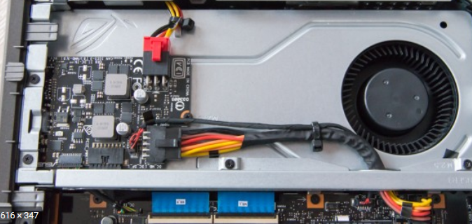
Look at this thing, it’s crazy tiny. same size of the actual gpu lmao.
Here you can see the mounting mechanism of the GR8, the cooler bolts directly to the socket bracket mounts. So theoretically it would be possible to do a direct die cooling with liquid metal.
Maybe if i get crazy ill be able to do even a custom case for it and do some water cooling madness.
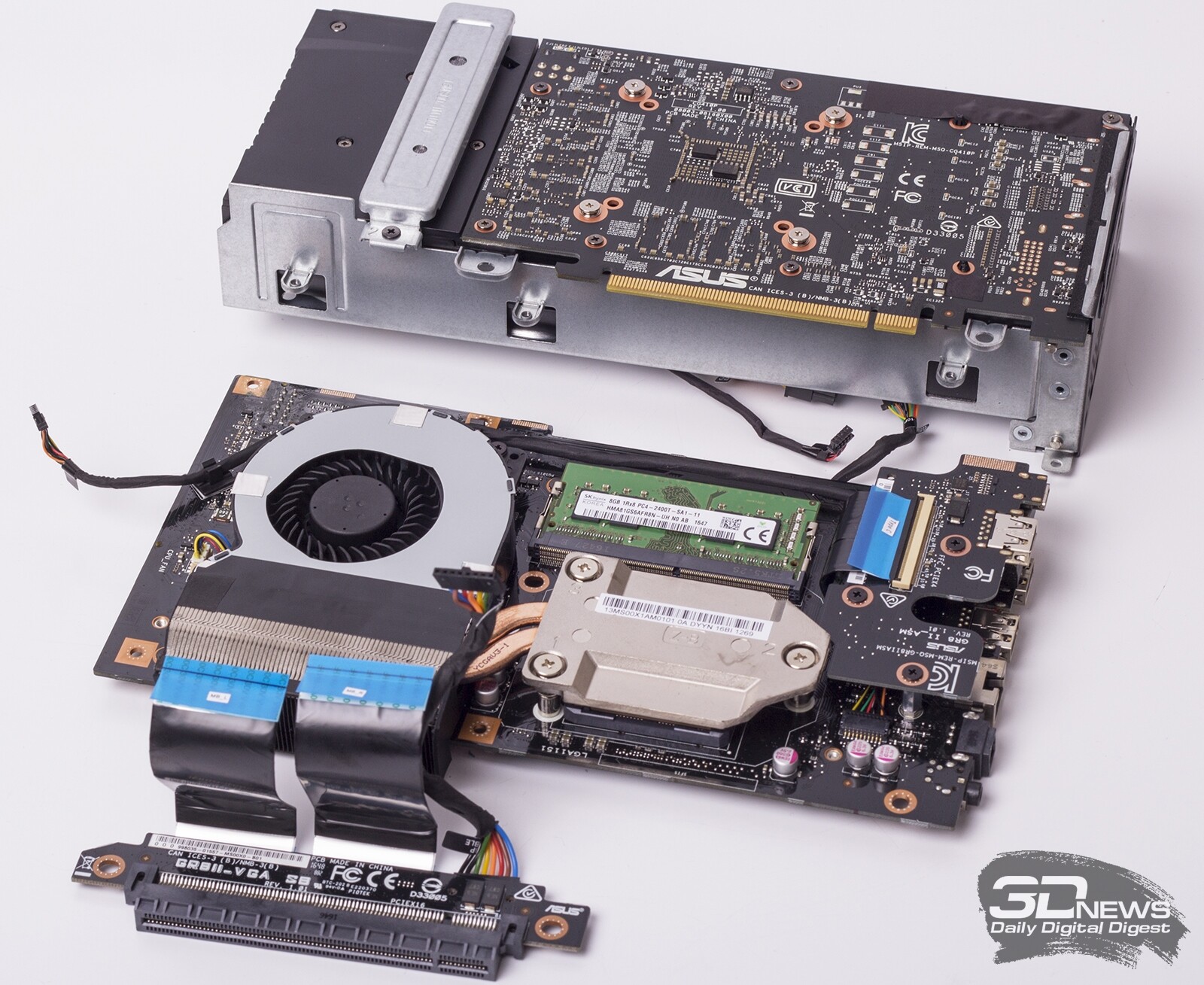
Dont forget the CPU VRM. On G20xx boards that VRM is powered from the 19,5V rail and not from 12V. You should verify if it is 12V or 19,5V. That tiny hookup board (on top of GPU) looks like a 12V, 5V, 3.3V PSU for peripheral things only (HDD …)
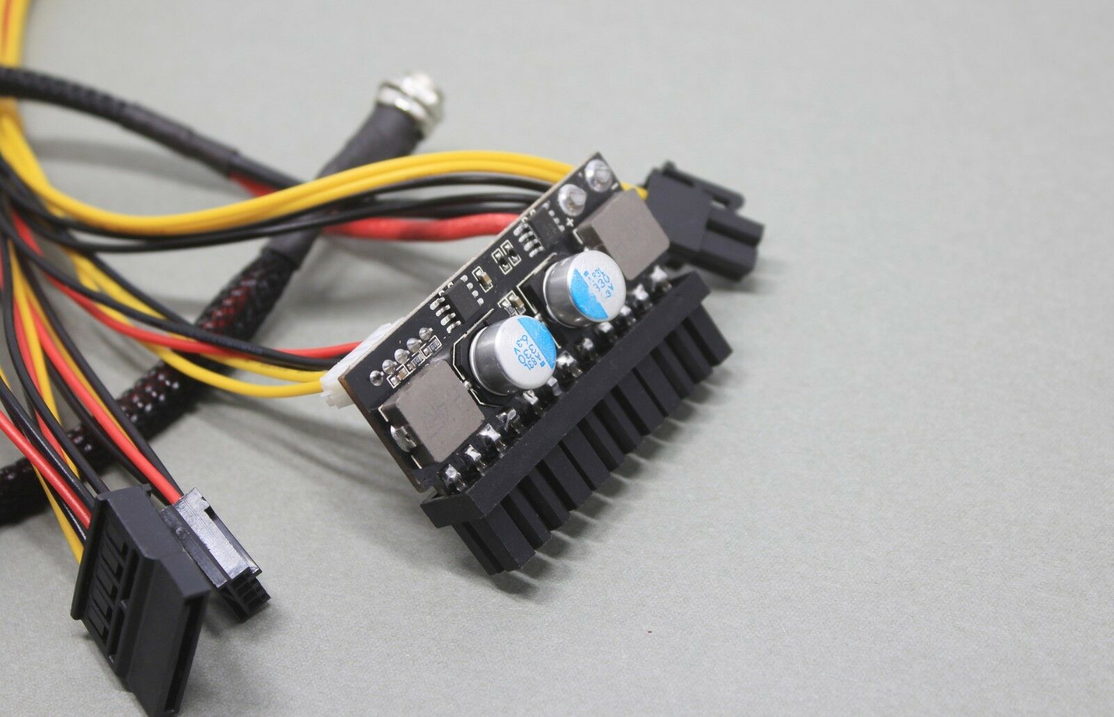
Yes i know that. But the pico-psu mod that im talking about is for the GR8 II. Since it only has 230W of available power from the brick…
If i manage to attach to GR8 II a pico psu like this one i should be able to run an extra 6/8 PIN gpu power connector and also some axtra fans and maybe a liquid cooling setup too with a fan controller.
I’m just not sure if the two pico psues could work together. In theory they should…
ok, misunderstood. Thought, you wanted to replace the complete PSU unit. Powerring the GPU from another PSU will work. I did it on another pc, where i hadn´t the matching adapters.
Yeh, theres no point for me to mess with input power of the G20CB since it alredy has planty enough for my needs (230W+180W).
But the GR8 doesnt…
What do you think? could those two pico psu work together? I see that theres also the power on line coming from the motherboard to the oem pico psu.
I could line it to the aftermarket pico psu just to see if it at the very least power on correctly xD
It could work. just try it.
I wish i could. Dont have one at hand… I’ll probably buy one soon, theyr cheap af.
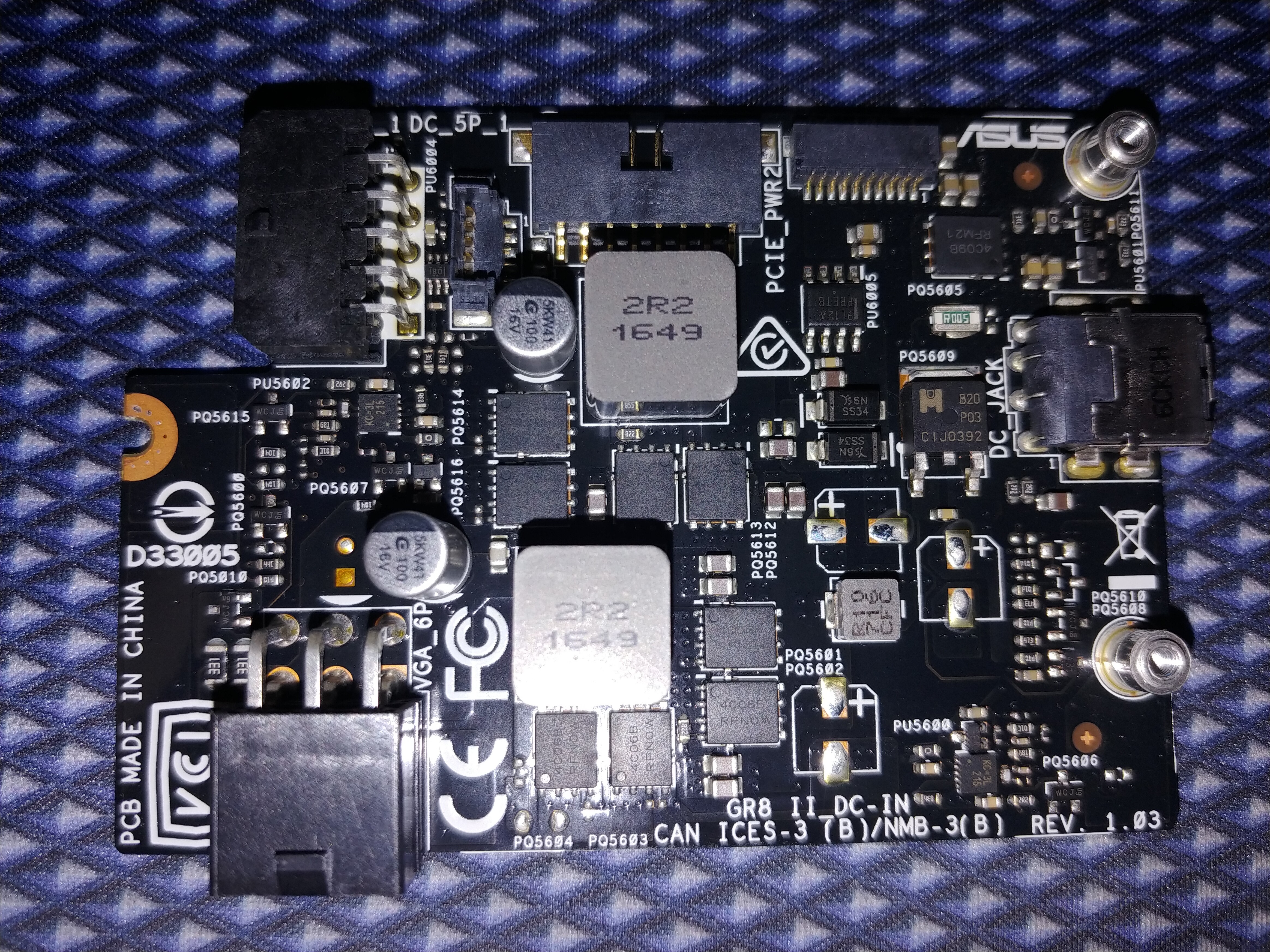
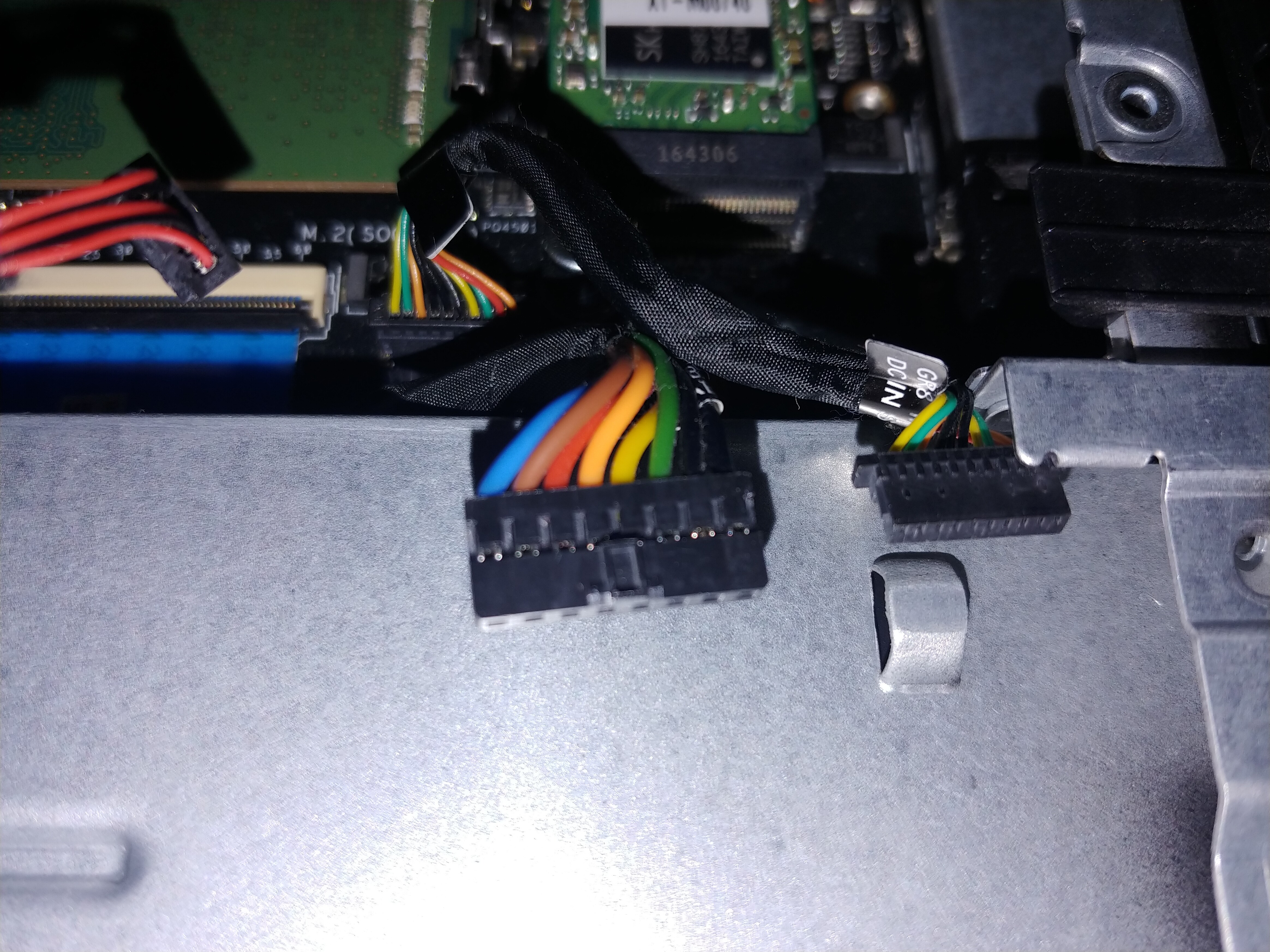
These are some close-in photos of the power board. Just finished putting it all back together…
Biostar b250 gtn
Hi, first of all thanks for the mod. I’m having problems with the computer refusing to start after putting in the pin modded 9900K. Any suggestions?
I am using an ASRock z270 Fatal!ty ac/itx board. I made the mod using the Coffee Lake Tool for an R0 9900K. The motherboard had never been updated so I used the most up to date stock BIOS for the mod and it updated to the 11.7.1229 ME provided by the mod.
I tried the pin mod using conductive ink, then tried the pencil method just to see, and then went back to the conductive ink. I’m using kapton tape to isolate. I first tried isolating based on the P0 image in this thread’s post then tried the ASRock (only two pins) isolated pins version. None worked.
The motherboard boots fine and was stable after the update to the modded bios with my i5 6440. I checked the ME in the UEFI page.
I am at a loss at what else to do except switch to conductive tape for the two connected pins? Maybe some one can check BIOS file and double check my pin mods…
Photos and modded BIOS here:
https://mega.nz/folder/xtozgASZ#KUNSfW5dkrPZx3RQKHMklg
Thanks in advance!
???
acknowledgement
CodeRush: UEFITool and other tool author
Fernando: Win-Raid owner
SoniX: UBU tool author
platomav: ME Analyzer
Mov AX, 0xDEAD: PCIE patcher
s.napi: Fixing HT
dsanke: many research info
???
Process file "D:\tool mode\CoffeeLake MOD tool\Coffee_Lake_Mod_Tool\H110M-E-M2-A
SUS-4210.CAP"
Choose Target CPU :
B0:
G49x0(T),G5420(SR3YH),G55x0(T),G56x0(T),8100(T),8300(T),8350K,
9100(T),9100F(SRF7W),9300(T),9350(K,F)
U0:
G54x0(T),8400(T),8500(T),8600(K),8700(T,K),8086K,
9100F(SRF6N),9400(SR3X5),9400F(SRF6M),9500,9500F(SRF6Q),9600
P0:
9400(SRELV),9400F(SRFAH),9600K(SRELU),9600KF(SRFAD),
9700KF(SRFAC),9700K(SRELT)
R0:
9400(SRG0Y),9400F(SRG0Z),9500F(SRG10),9600K(SRG11),
9600KF(SRG12),9700(SRG13),9700F(SRG14),9700K(SRG15),9700KF(SRG16)
?B0:1? ?U0:2? ?P0:3? ?R0:4? ???:5? ???: 1
================================================================
brand: ASUSTeK
Mainboard: H110M-E_M.2
Version:4210
Save CAP as bin format
FLASHBACK Name H110MEM2.CAP
Done!
================================================================
ME Version of BIOS is 11.8.65.3590
ME TYPE of BIOS is Consumer
Chipest H110
Replace ME Version to 11.7.0.1229
Done!
================================================================
Ready Update GOP & VBIOS…
VBIOS ver:File can’t be opened.
error happen…
Press any key to continue . . .
================================================================
Enalbe CPU PCIE …
bios need with KabyLake support, Please check
If your MB brand is asus and bios verion very new(3805,1205)
or asrock 100 series, ignore this warming and continue
Press any key to continue . . .
================================================================
Ready to Insert CPU MicroCode…
Insert into Vol[67AB]: 04
Insert into Vol[67AB]: 05
additional insert[8CD]:03
Done!
???
Congratulations
>>: "D:\tool mode\CoffeeLake MOD tool\Coffee_Lake_Mod_Tool\ASUSTeK_H110M-E_M.2_4
210.CON117.678ABCD.bin"
JOB Done
Press any key to exit
Please check for me!
Ready Update GOP & VBIOS…
VBIOS ver:File can’t be opened.
error happen…
Press any key to continue . . .
Hello
I just get 9900k R0 stepping ( SRG19 ). I try to make it work with ASUS IX Apex. But the newest version makes an error durring BMP, I have replaced SSF.exe and no luck.
With older updated version the process will finish with no problem but the board will stom on code 91.
Can you please help me or send me updated bios?
Thank you
@kiklop32 Dsanke has made several specific modded BIOS ported from the Apex X but you will need a programmer to flash.
Author: @dsanke
Motherboard: ASUS ROG MAXIMUS IX APEX
Based on:ASUS ROG MAXIMUS X APEX 2301
ME: 11.7.0.1261
Microcodes: The same as original M10A BIOS.
Note: Flash via SPI Programmer. Check Readme.txt in archive for detail. Do not use this BIOS with 6/7th gen CPU , Intel’s new RC code may not compatible with old CPU.
ROG-MAXIMUS-IX-APEX-ASUS-2301.7z
There is a readme included that explains all modificiations.
chinobino
Thank you man. It is working now ![]()
I will test it more tomorrow.
I did not need the programmer as normal bios flash with bios button on MB worked with no issue. I have bridged two pads on MB to avoid biosflash check.
Thanks @easlan
I will try it this weekend. Hopefully able to bring those RGB back.
@Rez - If you want to do Coffee mod, best to use flash programmer, dump BIOS, edit, program back
@Pumpkin317 - BIOS is not in EXE, I just downloaded from site - http://www.biostar-usa.com/app/en-us/mb/…ID=875#download
http://www.biostar-usa.com/app/en-us/biosdl.php?BID=4779 << Direct BIOS Download link, same as clicking BIOS download button at above linked page
@Lamda - Isolate per Asrock marked colors on this image at section 3.2 - https://translate.google.com/translate?s…78%26start%3D60
Connect with conductive ink should work, provided you cleaned off the pencil first and that the ink is actually conductive.
However, I see an issue with your 2xx board and i9, see image at 4.1 in above linked guide, you can’t use this CPU on this board with mod stock Z270 BIOS.
You need ported BIOS from Asrock Fatal1ty Z370 Gaming-ITX/ac
@dsanke @chinobino - Is there already Asrock Z270 Gaming-ITX/ac >> Z370 Ported BIOS?
@Lost_N_BIOS No sorry, I have not seen it.
Thanks @chinobino - If dsanke says no too, this may be my first manual attempted port BIOS 
@Lamda - Do you have flash programmer, like CH341A or other?
@Lost_N_BIOS No but I can get one quick. This motherboard took the modded BIOS/ME without errors so I didn’t think I needed one. Thank you for attempting a port!
Should I spend a little more and get a EZP2019 USB Programmer or a basic CH341A USB Programmer is good enough?