Beta BIOS with TPM support for Huananzhi TF/F8/T8/TF-Q, looking for testers
Using the BD4 and CD4 BIOS as basis, I have put together the following:
Old TF/F8/T8 (NCT5532D)
New TF/F8/T8 (NCT5567D-B)
TF-Q
If you have an external programmer, then send me a PM with the following info:
What board(s) you have. If not TF-Q, then also state 5532D or 5567D-B
What CPU(s) you will test with
How many RAM sticks you will test with
I will then send you a link. Please note that I do not have any of these boards in hand, and can therefore only rely on feedback after you have tested.
I am the owner of the board X99D4M4 on the C612 chipset and processor 1660V3 overclock 4.2Ghz. I decided to make a mod with the addition TPM and Secure Boot…
I flashed your BIOS that was posted earlier.I flashed your BIOS that was posted earlier FIB_X9MPM005_250827.(It works perfectly but there is no overclocking)
The TPM module worked great (thank you for the pinout of the debug connector with D3M4)
I used the TPM module from the OZON marketplace.
But there is a small problem(
On a more recent BIOS I encountered a number of problems
The overclocking option is available but your latest BIOS is going crazy.
The temperature is displayed incorrectly (above 100C)
The speeds of the water pump and its coolers are displayed as N/A
Also, after attempting to overclock, the board bricks until you flash it again with an external programmer.
I would really like to receive instructions or a ready-made BIOS with overclocking capabilities)
There is also a fee D4M4 on-chip BIOS XMC, she doesn’t accept anything other than her native BIOS.
Ready to become a BIOS tester
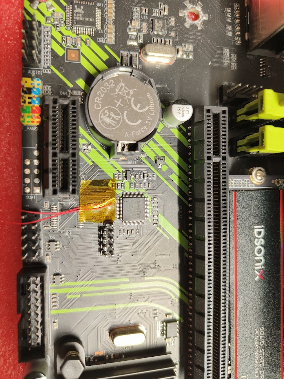
A little later I’ll send you how I redesigned the TPM module for convenient connection to the board, because D4M4 the debug connector has a non-standard pinout, unlike other x99 boards.
Hello and welcome! Glad you got TPM up and running, and new ideas on how to do things like physical TPM installation are always welcome! So let us see what can be done for overclocking you 1660V3. But let us start with this statement:
I did all my TBU (Turbo Boost Unlock) testing on X99D3M4. It is a DDR3 board, so I used a 2666V3 CPU
I did all my 1660V3 testing on ZX-99EV3. Before testing, I used Intel FITC and verified that the Management Engine is identical between X99D3M4 and ZX-99EV3
I can see from your post that you are capable with both hardware and software, so I think you can actually put together your own CPU overclocking BIOS
Step 2: Download the Machinist X99-U9 BIOS from this post
Step 3: Follow “Swapping regions with UEFITool 0.28.0” in the last part of the first post. Take the BIOS region from “X99-U9_with_CPU_OC.bin” and replace it in “D1_M2_B2_251005.bin”. Save as a new file and flash.
Regarding XMC flash chip: Recently I have also gotten CPU overclocking working with an updated Angxun BIOS (X99-DS4). But basically I am hoping that there will be an updated Huananzhi BD4 BIOS with XMC flash support soon. It really is the best BIOS there is.
As you see you’ll need an optional signal straight from the NCT5332D chipset, so some soldering skills are required if you want the full set of connections.
Really appreciate your contribution, but I do have some suggestions:
I think pin 3 of your LPC_DEBUG is CLK (same as my X79 board). Also you don’t need SERIRQ for the TPM module to work (at least I’m not using it right now). All in all, I believe FIB’s way of connecting TPM module using 2.54 dupont wires is way more easily achievable.
The issue is that the PR9 has 2.0mm pitch headers, which are a bit nasty. I haven’t found a double row header 2.0mm pitch 2x5pin header that goes to 2.54mm dupont lines on AliExpress.
I’ll measure the output on pin 3 tomorrow again with my oscilloscope to see if it’s indeed PCICLK.
Oh that’s such a pain. I can’t even found a single dupont 2.0mm female to 2.54mm male on Aliexpress too. Worst case scenario you can order anything with 2.0mm pitch to dupont 2.54mm male here. When plugging it to the LPC_DEBUG header, you might need to scrape off bit of the plastic housing.
2.0 mm pitch header on top of the motherboard simply means that you can buy corresponding 2.0 mm wires and a more “standard” TPM LPC module. For instance 14 pin MSI or ASUS should work, since they both are 2.0mm pitch. In other words: It seems really unnecessary, complicated and even a bit risky to solder wires on underneath the motherboard, when you already have a fairly standard header available on top. At the bottom of this post is how I installed the TPM underneath my ZX-99EV3 using nothing but wires and electrical vinyl tape. Sits perfectly installed in a case that way, since the standoffs are a few mm taller than the TPM module.
The official PR9-H and PR9-H 2.0 BIOS both support TPM, and that might get the fan functionality back. But a quick look with Intel FITC shows me that the official PR9 comes with an H81 chipset. So if I were you, I would absolutely try the Huananzhi BD4 BIOS instead.
Lastly I could be completely wrong but: If the aim is to use TPM 2.0 functionality and not TPM 1.2, then I do not think you need to solder wires onto the chipset either. I know with 100% certainty that I did not need to do that with the three boards I have verified myself (X99Z V102, ZX-99EV3, X99D3M4). See my instructions/measurements. Only 9 wires were needed, PCICLK and SERIRQ was not needed.
An update for those who want to try the same thing:
I ordered two additional PR9 motherboards but the modded BIOS does not work on them.
The differences I noticed:
The original working PR9 had an Q87 chipset, the 2nd batch had Q85 chipsets.
The original working PR9 had an MXIC bios chip, the 2nd batch both had FM25W128 bios chips.
Be careful before you start with this mod. I will do further research to see if I can get the new boards working.
Update: I’ve tried the BD4 bios (D1 M1 B1), but so far no success. The power supply clicks and switches off after less than 1 second and restarts in an endless loop. Different behavior than from the P4-based bios, where the motherboard powers on, but everything just stays blank. I’ll try more images after work.
I had a quick look at the BD4 BIOS, and “MXIC 25L/U Series” and “Fudan FM25Q Series” flash chip should work just fine. But it seems that you need support for “Fudan FM25W Series”. The SPI ID for this flash chip is “A12818” according to section 10.1.1 of the datasheet. And I can indeed see this ID in the flash descriptor of the official PR9 BIOS.
The good news is that it will not be the same difficult situation as I had with the XMC chips for almost two years. I can already find support for this Fudan flash in the latest BIOS for
Take your working 16M PR9 BIOS file as a starting point
Use Uefitool to extract just the BIOS region (seems this is what you already did)
Replace the BIOS region in your working 16M PR9 BIOS file
Save to a new file, and flash with an external programmer
And thanks for giving me a heads up about the P4 BIOS, I will check and test this one further. A quick look at it tells me that you can indeed use AMIBCP and unhide the controls over Fan 2. It is currently set to “Full on Mode” instead of “Automatic Mode”.