Hi,
I would like to put the HYPER M.2 X16 CARD@ x16 speed. Unfortunately, what I get today is just x8. I have 4 m.2 ssd on it.
Here’s my config :
MOBO : ROG Rampage VI Extreme
CPU: i9-7940X (48 Lanes)
RAM : GSkill-Trident-RGB Z 32GB
GC : GTX 1070 TI
I put the HYPER M.2 X16 CARD on a x16 PCIE slot, but no chance.
So with some research, it look like as the bios does not support pcie bifurcation as it should.
The need is to put this PCIE slot at x4x4x4x4 but I don’t have any option to do it as we can on another motherboards from another constructors.
So would you be so kind as to modify the bios and activate the related options please?
I have already tried but unfortunately I have not succeeded. So I am counting on your help, and would like to know how to achieve this feat so that I too can learn.
Here is the link for the bios
Download latest Bios here
Thank you so much.
@danielp87 - On the BIOS main page, find your ME FW version (Or in large window, motherboard section with HWINFO64). Then download matching Intel ME System Tools package from this thread
Intel Management Engine: Drivers, Firmware & System Tools
Inside you will find a flash programming tools folder, and inside that a windows/win/win32 folder. Select that win folder, hold shift and press right click, choose open command window here (not power shell)
Then dump BIOS region using this command >> FPTw.exe -bios -d biosreg.bin
Zip and upload that file for me to modify, this way you don’t loose serial, UUID etc.
Hello,
thank you for your answer.
please find attached the requested file.
If you could enable everything that would be interesting.
Thank you and have a good day.
biosreg.zip (5.63 MB)
@danielp87 - Thanks for backup, I’ll see what I can do. Wow, up to 18 cores supported on this beast! Also, that’s a very unusual AMI BIOS 
So, what did you already try that didn’t work? Did you try making the changes using grub w/ setup_var and it failed?
Since this wont open in any AMIBCP version, I assume maybe that’s all that’s left to try, aside from manually making the changes via IFR/Hex. Or did you try that too and nothing?If you’re here now, can you please add a zip of images of all the main sections of the BIOS you can see now, no need to drill into submenus or subsections, just a shot of each of the main screens will be fine (like 1 each of Main, Extreme Tweaker, Advanced, Monitor, Boot, Tool, Exit)
Never mind, I found in a few reviews  This is like Z170-A and Pro Gaming BIOS I’ve modified, same look.
So I know now, if I enabled any invisible menus for you, they wont appear due to the layout/GUI images in place are actual images for each tab and not sized with whatever text is there, but you can scroll over to them (Like keep scrolling/tabbing past exit and it’s there even though you can’t see name
Do you have flash programmer like CH341A or other? If not, does this board have BIOS switches where you can switch between Main and Backup BIOS, for recovery in case of bad flash?
I found all this in setup IFR, which we can change via grub w/ setup_var, but I think I can enable this hidden menu section for you anyway, so may not need to do that
Here’s my grub/setup_var guide though in case you want to play/test before I get you a BIOS made
[GUIDE] Grub Fix Intel FPT Error 368 - BIOS Lock Asus/Other Mod BIOS Flash
Anything in spoilers below, I can make visible for you if not already (Usually), or I can change default setting being used while leaving option hidden (always possible).
Or any of this can be changed using guide method above, it’s written to change a single setting “BIOS Lock”, but same method applies to anything you find in Setup IFR output
One Of Option: Auto, Value (8 bit): 0x0 (default) {09 07 D6 00 10 00 00}
One Of Option: Gen1, Value (8 bit): 0x1 {09 07 D7 07 00 00 01}
One Of Option: Gen2, Value (8 bit): 0x2 {09 07 D8 07 00 00 02}
One Of Option: Gen3, Value (8 bit): 0x3 {09 07 D9 07 00 00 03}
One Of: Enable Root Port, VarStoreInfo (VarOffset/VarName): 0x774, VarStore: 0x1, QuestionId: 0x529, Size: 1, Min: 0x0, Max 0x2, Step: 0x0 {05 91 F3 06 F6 06 29 05 01 00 74 07 10 10 00 02 00}
One Of Option: Disabled, Value (8 bit): 0x0 {09 07 D8 00 00 00 00}
One Of Option: Enabled, Value (8 bit): 0x1 {09 07 D7 00 00 00 01}
One Of Option: Auto, Value (8 bit): 0x2 (default) {09 07 D6 00 10 00 02}
One Of: Max Link Width, VarStoreInfo (VarOffset/VarName): 0x77A, VarStore: 0x1, QuestionId: 0x52A, Size: 1, Min: 0x0, Max 0x4, Step: 0x0 {05 91 70 06 73 06 2A 05 01 00 7A 07 10 10 00 04 00}
One Of Option: Auto, Value (8 bit): 0x0 (default) {09 07 D6 00 10 00 00}
One Of Option: Force X1, Value (8 bit): 0x1 {09 07 74 06 00 00 01}
One Of Option: Force X2, Value (8 bit): 0x2 {09 07 75 06 00 00 02}
One Of Option: Force X4, Value (8 bit): 0x3 {09 07 76 06 00 00 03}
One Of Option: Force X8, Value (8 bit): 0x4 {09 07 77 06 00 00 04}
PEG0 Physical Slot Number 0x1 Max Link Width, VarStoreInfo (VarOffset/VarName): 0x77B, VarStore: 0x1, QuestionId: 0x53B, Size: 1, Min: 0x0, Max 0x3, Step: 0x0 {05 91 71 06 73 06 3B 05 01 00 7B 07 10 10 00 03 00}
One Of Option: Auto, Value (8 bit): 0x0 (default) {09 07 D6 00 10 00 00}
One Of Option: Force X1, Value (8 bit): 0x1 {09 07 74 06 00 00 01}
One Of Option: Force X2, Value (8 bit): 0x2 {09 07 75 06 00 00 02}
One Of Option: Force X4, Value (8 bit): 0x3 {09 07 76 06 00 00 03}
PCIEX8_4 bandwidth configuration, VarStoreInfo (VarOffset/VarName): 0x1218, VarStore: 0x1, QuestionId: 0xDBB, Size: 1, Min: 0x0, Max 0x1, Step: 0x0 {05 91 0C 23 0D 23 BB 0D 01 00 18 12 10 10 00 01 00}
One Of Option: Auto, Value (8 bit): 0x0 (default) {09 07 06 00 10 00 00}
One Of Option: X8 mode, Value (8 bit): 0x1 {09 07 0E 23 00 00 01}
One Of: DIMM.2, and U.2, VarStoreInfo (VarOffset/VarName): 0x1216, VarStore: 0x1, QuestionId: 0x293B, Size: 1, Min: 0x0, Max 0x4, Step: 0x0 {05 91 8B 22 90 22 3B 29 01 00 16 12 14 10 00 04 00}
One Of Option: Disabled, Value (8 bit): 0x0 (default) {09 07 05 00 10 00 00}
One Of Option: DIMM.2 + U2, Value (8 bit): 0x4 {09 07 94 22 00 00 04}
PCIEX16_3 Link Speed, VarStoreInfo (VarOffset/VarName): 0x779, VarStore: 0x1, QuestionId: 0x54C, Size: 1, Min: 0x0, Max 0x3, Step: 0x0 {05 91 FB 06 FC 06 4C 05 01 00 79 07 10 10 00 03 00}
One Of Option: Auto, Value (8 bit): 0x0 (default) {09 07 D6 00 10 00 00}
One Of Option: Gen1, Value (8 bit): 0x1 {09 07 D7 07 00 00 01}
One Of Option: Gen2, Value (8 bit): 0x2 {09 07 D8 07 00 00 02}
One Of Option: Gen3, Value (8 bit): 0x3 {09 07 D9 07 00 00 03}
One Of: Max Link Width, VarStoreInfo (VarOffset/VarName): 0x77C, VarStore: 0x1, QuestionId: 0x54D, Size: 1, Min: 0x0, Max 0x2, Step: 0x0 {05 91 72 06 73 06 4D 05 01 00 7C 07 10 10 00 02 00}
One Of Option: Auto, Value (8 bit): 0x0 (default) {09 07 D6 00 10 00 00}
One Of Option: Force X1, Value (8 bit): 0x1 {09 07 74 06 00 00 01}
One Of Option: Force X2, Value (8 bit): 0x2 {09 07 75 06 00 00 02}
Also, very much directly related to your main device issue, I find these (Disabled by default for all)
These may be the only ones needed changed, I mean changing these, whichever slot you need, may change all other required settings by default once you enable whichever one of the Hyper Options you need
Do you have “CPU Storage Configuration” Submenu inside advanced section? I see it in review images, this is where the options below are located. See images 7+8 here https://proclockers.com/reviews/motherbo…review/page/0/4
I also see these present in the PDF (Set Hyper or X4 mentioned for the settings below - (VROC)= Virtual RAID ON CPU & (Data) I assume single drives or managed some other way, unclear and not covered by the gude?) - https://dlcdnets.asus.com/pub/ASUS/mb/Ad…e_EM_V4_WEB.PDF
However, the above PDF, makes it seem like these options maybe only for Intel RAID, AMD RAID setup uses different BIOS settings to enable RAID on this device, but check it out anyway so you’re sure what’s what (Since I’ve not used one of these) I did see you have Intel CPU though, so I assume these are for you

CPU Storage Configuration, FormId: 0x2935 {01 86 35 29 85 22}
0x808B9 One Of: PCIEX16/X8_1, VarStoreInfo (VarOffset/VarName): 0x1212, VarStore: 0x1, QuestionId: 0x2936, Size: 1, Min: 0x0, Max 0x3, Step: 0x0 {05 91 87 22 8C 22 36 29 01 00 12 12 14 10 00 03 00}
One Of Option: Disabled, Value (8 bit): 0x0 (default) {09 07 05 00 10 00 00}
One Of Option: PCIE SSD X4 Card, Value (8 bit): 0x1 {09 07 91 22 00 00 01}
One Of Option: Hyper M.2 X16 (VROC), Value (8 bit): 0x2 {09 07 92 22 00 00 02}
One Of Option: Hyper M.2 X16 (Data), Value (8 bit): 0x3 {09 07 93 22 00 00 03}
One Of: PCIEX8_2, VarStoreInfo (VarOffset/VarName): 0x1213, VarStore: 0x1, QuestionId: 0x2937, Size: 1, Min: 0x0, Max 0x3, Step: 0x0 {05 91 88 22 8D 22 37 29 01 00 13 12 14 10 00 03 00}
One Of Option: Disabled, Value (8 bit): 0x0 (default) {09 07 05 00 10 00 00}
One Of Option: PCIE SSD X4 Card, Value (8 bit): 0x1 {09 07 91 22 00 00 01}
One Of Option: Hyper M.2 X16 (VROC), Value (8 bit): 0x2 {09 07 92 22 00 00 02}
One Of Option: Hyper M.2 X16 (Data), Value (8 bit): 0x3 {09 07 93 22 00 00 03}
One Of: PCIEX8_2, VarStoreInfo (VarOffset/VarName): 0x1214, VarStore: 0x1, QuestionId: 0x2938, Size: 1, Min: 0x0, Max 0x3, Step: 0x0 {05 91 88 22 8D 22 38 29 01 00 14 12 14 10 00 03 00}
One Of Option: Disabled, Value (8 bit): 0x0 (default) {09 07 05 00 10 00 00}
One Of Option: PCIE SSD X4 Card, Value (8 bit): 0x1 {09 07 91 22 00 00 01}
One Of Option: Hyper M.2 X16 (VROC), Value (8 bit): 0x2 {09 07 92 22 00 00 02}
One Of Option: Hyper M.2 X16 (Data), Value (8 bit): 0x3 {09 07 93 22 00 00 03}
One Of: PCIEX16/X8_3, VarStoreInfo (VarOffset/VarName): 0x1215, VarStore: 0x1, QuestionId: 0x2939, Size: 1, Min: 0x0, Max 0x3, Step: 0x0 {05 91 89 22 8E 22 39 29 01 00 15 12 14 10 00 03 00}
One Of Option: Disabled, Value (8 bit): 0x0 (default) {09 07 05 00 10 00 00}
One Of Option: PCIE SSD X4 Card, Value (8 bit): 0x1 {09 07 91 22 00 00 01}
One Of Option: Hyper M.2 X16 (VROC), Value (8 bit): 0x2 {09 07 92 22 00 00 02}
One Of Option: Hyper M.2 X16 (Data), Value (8 bit): 0x3 {09 07 93 22 00 00 03}
One Of: PCIEX8_4, DIMM.2, and U.2, VarStoreInfo (VarOffset/VarName): 0x1216, VarStore: 0x1, QuestionId: 0x293A, Size: 1, Min: 0x0, Max 0x5, Step: 0x0 {05 91 8A 22 8F 22 3A 29 01 00 16 12 14 10 00 05 00}
One Of Option: Disabled, Value (8 bit): 0x0 (default) {09 07 05 00 10 00 00}
One Of Option: PCIE SSD X4 Card, Value (8 bit): 0x1 {09 07 91 22 00 00 01}
One Of Option: Hyper M.2 X16 (VROC), Value (8 bit): 0x2 {09 07 92 22 00 00 02}
One Of Option: Hyper M.2 X16 (Data), Value (8 bit): 0x3 {09 07 93 22 00 00 03}
One Of Option: DIMM.2 + U2, Value (8 bit): 0x4 {09 07 94 22 00 00 04}
One Of Option: All Devices, Value (8 bit): 0x5 {09 07 95 22 00 00 05}
I also see this for all slots (0-24) (Not all same setting defaults for each though, I think, but I think these are related too)
PCIEX4_1/PCH M.2_1(DIMM.2) PCIE Storage RAID Support, VarStoreInfo (VarOffset/VarName): 0xF27, VarStore: 0x1, QuestionId: 0x6A4, Size: 1, Min: 0x0, Max 0x1, Step: 0x0 {05 91 BB 0C BD 0C A4 06 01 00 27 0F 14 10 00 01 00}
One Of Option: Enabled, Value (8 bit): 0x1 {09 07 04 00 00 00 01}
One Of Option: Disabled, Value (8 bit): 0x0 (default) {09 07 05 00 10 00 00}
And this, on all ports 0-24, general examples of a few of the settings in each, once you generate IFR output from setup module you can see all
PCIe Storage Dev On Port 23, VarStoreInfo (VarOffset/VarName): 0xF29, VarStore: 0x1, QuestionId: 0x6A5, Size: 1, Min: 0x0, Max 0x1, Step: 0x0 {05 91 BC 0C BD 0C A5 06 01 00 29 0F 14 10 00 01 00}
One Of Option: Enabled, Value (8 bit): 0x1 {09 07 04 00 00 00 01}
One Of Option: Disabled, Value (8 bit): 0x0 (default) {09 07 05 00 10 00 00}
PCIe Storage Dev On Port 7, VarStoreInfo (VarOffset/VarName): 0xF19, VarStore: 0x1, QuestionId: 0x69D, Size: 1, Min: 0x0, Max 0x1, Step: 0x0 {05 91 B4 0C BD 0C 9D 06 01 00 19 0F 14 10 00 01 00}
One Of Option: RST Controlled, Value (8 bit): 0x1 {09 07 AF 0C 00 00 01}
One Of Option: Not RST Controlled, Value (8 bit): 0x0 (default) {09 07 B0 0C 10 00
M.2_1 PCIE Storage RAID Support, VarStoreInfo (VarOffset/VarName): 0xF1B, VarStore: 0x1, QuestionId: 0x69E, Size: 1, Min: 0x0, Max 0x1, Step: 0x0 {05 91 B5 0C BD 0C 9E 06 01 00 1B 0F 14 10 00 01 00}
One Of Option: Enabled, Value (8 bit): 0x1 {09 07 04 00 00 00 01}
Hi, very interesting.
What I tried is, with IFR/HEX, to change the function supress if 46 02 by 47 02 (as explained here.)
Didn’t try tabbing past exit on bios. will try tonight.
No I don’t have a flash programmer like CH341A. Yes she has Bios switchs.
I remember tried to find the “BIOS Lock” but no chance. maybe my search was not good.
Yes I have “CPU Storage Configuration” I can enable vroc on a pcie slot but I can’t set the lane parameter.
I am interested in VMD (I would like to have a bootable disk) which is the case today but not at maximum speed.
I will have a look into this and keep you in touch about my progress.
Thank you very much !!!
Tabbing past exit only applies to another method of editing, that’s not required on this to enable other main menus (None are hidden, like no second advanced or chipset etc)
So what I mentioned about that doesn’t apply here, but if it did it would only apply to if you enabled other entire menu like chipset or second advanced etc. then it would be blindly hiding behind/past exit tab.
46 to 47 should work, what setting did you try to unsuppress? Did you also, on top of that, enable in AMIBCP? Sometimes you need to do both, sometimes only one or the other will work, so if you only did the 46 to 47, try that plus AMIBCP, if that fails try AMIBCP only and no 46 to 47 edit.
BIOS lock is in the setup IFR, and enabled, search BIOS lock and you will find it. So, setting VROC does not change lane width/layout, sadly this BIOS does not have the hidden section many do with proper bifurcation settings, only what’s show above but no 4x4x4x4x or 8x8x etc
Did you try both DATA and VROC, both only give same lane width total? What lane width does it enable now, either of those, and did you try X4 setting instead? Try that one and see if it acts proper
I know lane width isn’t the main issue here, but if you’re only getting x8 when you should be getting x16 for example, that may be why it’s not going 4x4x4x4x like it should with the VROC Setting. You do have compatible CPU for this feature correct?
Hello,
Well, options 46 47 didn’t work. Tried to unsupress all settings with 46 value. maybee with those values changed in AMIBCP should show the options. (Usually, I get the tab Bios Strings with AMIBCP)
AMIBCP does not work with my bios unfortunately. The options are not displayed as for other motherboard bios.
“sadly this BIOS does not have the hidden section many do with proper bifurcation settings, only what’s show above but no 4x4x4x4x or 8x8x etc” in setup if I can see options for iio configuration as 4x4x4x4 or 8x8 or 4x did you see that ?
Yes tried both Data and Vroc.
yes normally X Series processors are compatible
https://www.intel.com/content/www/us/en/…d-software.html
Thank you
Ohh yes, sorry, I forgot AMIBCP does not work with your BIOS properly! There is no settings with 4x4x4x4 in your setup, here’s the IFR - http://s000.tinyupload.com/index.php?fil…482303425992444
* Edit >> Ohh, I see it now via UEFITool Unicode search, but it’s not in IFR output, this is only text string left in Base BIOS they built upon and didn’t remove, it’s not tied to any setting.
I’ll double check in assembly though, but I’ve seen stuff like this before, left over in strings but no where in settings hidden or visible, lazy coders  - #Edit, checked, nothing in the actual code, just the text strings
Yes, maybe needs AMIBCP edit too, but we can’t, AMIBCP changes settings in AMITSE/SetupData but the only way I know to know which bytes are what to change is by first editing in AMIBCP then compare, then you can do manually outside AMIBCP.
I’m sure there’s a way to figure it out, but I’ve not learned that yet. I do know you change 01 to 05 there for changing user access level from default to User, I’ve done this and compared changes etc with other BIOS. I’ll see if I can figure out how to get the offsets to make the changes manually without AMIBCP.
But the important setting we want isn’t there anyway
For now, on setup, lets pick a single setting you want but you can’t see, I will send you edited 2 ways, see if either work. If one does, I will show you what I did.
You pick, some setting from IFR, that’s in a subsection of Advanced that you can see within, but not the setting in question.
BTW, for your reference, here’s the menu info I gathered planning to unlock your BIOS for you, before I realized all main sections are visible and it can’t be opened with AMIBCP anyway. In case it helps you with anything on your end.
BIOS Lock = 0x912 IS Enabled
Rename to R6E.CAP for USB Flashback
Setup ------------ 0x2711 {01 86 11 27 07 00}
My Favorites ----- 0x2712 {0F 0F 6F 00 6F 00 01 00 00 00 FF FF 00 12 27}
Main ------------- 0x2713 {0F 0F 09 00 02 00 02 00 00 00 FF FF 00 13 27}
Extreme Tweaker – 0x2718 {0F 0F 1E 00 02 00 03 00 00 00 FF FF 00 18 27}
Advanced --------- 0x2719 {0F 0F 1F 00 02 00 04 00 00 00 FF FF 00 19 27}
Monitor ---------- 0x271C {0F 0F 20 00 02 00 05 00 00 00 FF FF 00 1C 27}
Boot ------------- 0x271E {0F 0F 23 00 02 00 06 00 00 00 FF FF 00 1E 27}
Tool ------------- 0x2720 {0F 0F 22 00 02 00 07 00 00 00 FF FF 00 20 27}
Exit ------------- 0x2721 {0F 0F 4D 00 02 00 08 00 00 00 FF FF 00 21 27}
Exit ------------- 0x2722 {01 86 22 27 4D 00} - Not used/blocked
Intel RC ACPI Settings - 0x2756 {01 86 56 27 CE 03}
@ 00177244 -
4a 10 59 7b 0d c0 58 41 87 ff f0 4d 63 96 a9 15 56 27 00 00 00 00 00 00 00 00 00 00 00 00 00 00
Enabled >> @00178b44 - 18 27 19 27 12 27 1c 27 1e 27 20 27 21 27 ff ff
@00177184 - blocked
4a 10 59 7b 0d c0 58 41 87 ff f0 4d 63 96 a9 15 11 27 00 00 00 00 00 00 00 00 00 00 00 00 00 00
4a 10 59 7b 0d c0 58 41 87 ff f0 4d 63 96 a9 15 22 27 00 00 00 00 00 00 00 00 00 00 00 00 00 00
55 c8 1b 94 7e bf cb 4f 88 2f 7a ea d1 5c 9d 47 00 00 00 00 00 00 00 00 00 00 00 00 00 00 00 00
04 f3 a9 ac e2 21 52 48 98 75 7f f4 88 1d 67 a5 00 00 00 00 00 00 00 00 00 00 00 00 00 00 00 00
04 5a 6d 51 d5 c0 57 46 b9 08 e4 fb 1d 93 5e f0 10 05 00 00 00 00 00 00 00 00 00 00 00 00 00 00
43 d6 87 ec a4 eb b5 4b a1 e5 3f 3e 36 b2 0d a9 01 00 00 00 00 00 00 00 00 00 00 00 00 00 00 00
4a 10 59 7b 0d c0 58 41 87 ff f0 4d 63 96 a9 15 56 27 00 00 00 00 00 00 00 00 00 00 00 00 00 00
@001514d4 - Enabled
4a 10 59 7b 0d c0 58 41 87 ff f0 4d 63 96 a9 15 13 27 00 00 07 10 00 00
4a 10 59 7b 0d c0 58 41 87 ff f0 4d 63 96 a9 15 19 27 00 00 08 10 00 00
4a 10 59 7b 0d c0 58 41 87 ff f0 4d 63 96 a9 15 1d 27 00 00 09 10 00 00
4a 10 59 7b 0d c0 58 41 87 ff f0 4d 63 96 a9 15 1e 27 00 00 0a 10 00 00
4a 10 59 7b 0d c0 58 41 87 ff f0 4d 63 96 a9 15 15 27 00 00 0b 10 00 00
4a 10 59 7b 0d c0 58 41 87 ff f0 4d 63 96 a9 15 21 27 00 00 0c 10 00 00
@00177064 - all
4a 10 59 7b 0d c0 58 41 87 ff f0 4d 63 96 a9 15 12 27 00 00 00 00 00 00 00 00 00 00 00 00 00 00
4a 10 59 7b 0d c0 58 41 87 ff f0 4d 63 96 a9 15 13 27 00 00 00 00 00 00 00 00 00 00 00 00 00 00
4a 10 59 7b 0d c0 58 41 87 ff f0 4d 63 96 a9 15 18 27 00 00 00 00 00 00 00 00 00 00 00 00 00 00
4a 10 59 7b 0d c0 58 41 87 ff f0 4d 63 96 a9 15 19 27 00 00 00 00 00 00 00 00 00 00 00 00 00 00
4a 10 59 7b 0d c0 58 41 87 ff f0 4d 63 96 a9 15 1c 27 00 00 00 00 00 00 00 00 00 00 00 00 00 00
4a 10 59 7b 0d c0 58 41 87 ff f0 4d 63 96 a9 15 1e 27 00 00 00 00 00 00 00 00 00 00 00 00 00 00
4a 10 59 7b 0d c0 58 41 87 ff f0 4d 63 96 a9 15 20 27 00 00 00 00 00 00 00 00 00 00 00 00 00 00
4a 10 59 7b 0d c0 58 41 87 ff f0 4d 63 96 a9 15 21 27 00 00 00 00 00 00 00 00 00 00 00 00 00 00
Thank you, I understand better now.
in parallel I opened a ticket at asus so that they could provide the desired option because asus actually advertises on their website for my motherboard so I’m waiting.
I could see in the IFR SocketIioConfig, I would eventually need this.
I confess I don’t know anything about modifying the bios, I’m learning.
I’m wondering if it would be possible to take code from another bios where the necessary option is supported and implement in ours
Thank you for your work
Yes, they should resolve this since they’re advertising it with the board!
You can see 4x4x4x4x in the IFR I uploaded for you? If not, what module did you get the IFR from, what GUID? Upload the IFR you are looking at, thanks
Many things are possibly to try like you mentioned, but you need flash programmer for recovery first, and you need to know what BIOS similar to your board has these options.
Show me image of CrystalDiskInfo with this drive selected. And also, download this tool and show me image with the drive/adapter selected, just want to see what it looks like in both of those
Utility to view some info on PCI devices
https://crystalmark.info/en/download/
No I don’t see it indeed but there is something mentioning SocketIIO
View71.htm is the Hwinfo report
and you have socketSetup IFR
the crystal disk info can’t see the drive ![]()
SocketSetup IFR.txt (798 KB)
VIEW71.zip (19.1 KB)
What about the two things I asked for images of, the programs in the links I gave above? Thanks for IFR, I will check it out. From your HWNINFO report I don’t even see this device? And I scrolled through it all.
On the Socket Config IFR, we can change the defaults, but without AMIBCP working, I can’t enable this menu, it’s not setup like the usual stuff in “Setup” so I’d need to see in AMIBCP to see if it shows up there and where.
Pick one, or a few you want me to change for a test run, all three with 4x4x4x4x option, set to that? Do you have onboard graphics, in case it messes up PCIE graphics?
If you run the above tool, the one linked here in the forum, I may be able to see from that which is the port the card is using now, maybe. Thanks, I see the image now, is that all you get, you don’t get lane width, lane speed, lane assignment etc on the right side of the program?
One Of: IOU0 (IIO PCIe Br1), VarStoreInfo (VarOffset/VarName): 0x32, VarStore: 0x1, QuestionId: 0x87, Size: 1, Min: 0x0, Max 0xFF, Step: 0x0 {05 91 95 02 A9 02 87 00 01 00 32 00 10 10 00 FF 00}
0x9EAE One Of Option: x4x4x4x4, Value (8 bit): 0x0 {09 07 B9 02 00 00 00}
0x9EB5 One Of Option: x4x4x8, Value (8 bit): 0x1 {09 07 BA 02 00 00 01}
0x9EBC One Of Option: x8x4x4, Value (8 bit): 0x2 {09 07 BB 02 00 00 02}
0x9EC3 One Of Option: x8x8, Value (8 bit): 0x3 {09 07 BC 02 00 00 03}
0x9ECA One Of Option: x16, Value (8 bit): 0x4 {09 07 B2 0D 00 00 04}
0x9ED1 One Of Option: Auto, Value (8 bit): 0xFF (default) {09 07 AF 0D 30 00 FF}
0x9ED8 End One Of {29 02}
0x9EDA One Of: IOU1 (IIO PCIe Br2), VarStoreInfo (VarOffset/VarName): 0x33, VarStore: 0x1, QuestionId: 0x88, Size: 1, Min: 0x0, Max 0xFF, Step: 0x0 {05 91 99 02 A9 02 88 00 01 00 33 00 10 10 00 FF 00}
0x9EEB One Of Option: x4x4x4x4, Value (8 bit): 0x0 {09 07 B9 02 00 00 00}
0x9EF2 One Of Option: x4x4x8, Value (8 bit): 0x1 {09 07 BA 02 00 00 01}
0x9EF9 One Of Option: x8x4x4, Value (8 bit): 0x2 {09 07 BB 02 00 00 02}
0x9F00 One Of Option: x8x8, Value (8 bit): 0x3 {09 07 BC 02 00 00 03}
0x9F07 One Of Option: x16, Value (8 bit): 0x4 {09 07 B2 0D 00 00 04}
0x9F0E One Of Option: Auto, Value (8 bit): 0xFF (default) {09 07 AF 0D 30 00 FF}
0x9F15 End One Of {29 02}
0x9F17 One Of: IOU2 (IIO PCIe Br3), VarStoreInfo (VarOffset/VarName): 0x34, VarStore: 0x1, QuestionId: 0x89, Size: 1, Min: 0x0, Max 0xFF, Step: 0x0 {05 91 9D 02 A9 02 89 00 01 00 34 00 10 10 00 FF 00}
0x9F28 One Of Option: x4x4x4x4, Value (8 bit): 0x0 {09 07 B9 02 00 00 00}
0x9F2F One Of Option: x4x4x8, Value (8 bit): 0x1 {09 07 BA 02 00 00 01}
0x9F36 One Of Option: x8x4x4, Value (8 bit): 0x2 {09 07 BB 02 00 00 02}
0x9F3D One Of Option: x8x8, Value (8 bit): 0x3 {09 07 BC 02 00 00 03}
0x9F44 One Of Option: x16, Value (8 bit): 0x4 {09 07 B2 0D 00 00 04}
0x9F4B One Of Option: Auto, Value (8 bit): 0xFF (default) {09 07 AF 0D 30 00 FF}
0x9F52 End One Of {29 02}
0x9F54 One Of: MCP0 (IIO PCIe Br4), VarStoreInfo (VarOffset/VarName): 0x35, VarStore: 0x1, QuestionId: 0x8A, Size: 1, Min: 0x4, Max 0xFF, Step: 0x0 {05 91 A1 02 A9 02 8A 00 01 00 35 00 10 10 04 FF 00}
0x9F65 One Of Option: x16, Value (8 bit): 0x4 {09 07 B2 0D 00 00 04}
0x9F6C One Of Option: Auto, Value (8 bit): 0xFF (default) {09 07 AF 0D 30 00 FF}
0x9F73 End One Of {29 02}
0x9F75 One Of: MCP1 (IIO PCIe Br5), VarStoreInfo (VarOffset/VarName): 0x36, VarStore: 0x1, QuestionId: 0x8B, Size: 1, Min: 0x4, Max 0xFF, Step: 0x0 {05 91 A5 02 A9 02 8B 00 01 00 36 00 10 10 04 FF 00}
0x9F86 One Of Option: x16, Value (8 bit): 0x4 {09 07 B2 0D 00 00 04}
0x9F8D One Of Option: Auto, Value (8 bit): 0xFF (default) {09 07 AF 0D 30 00 FF}
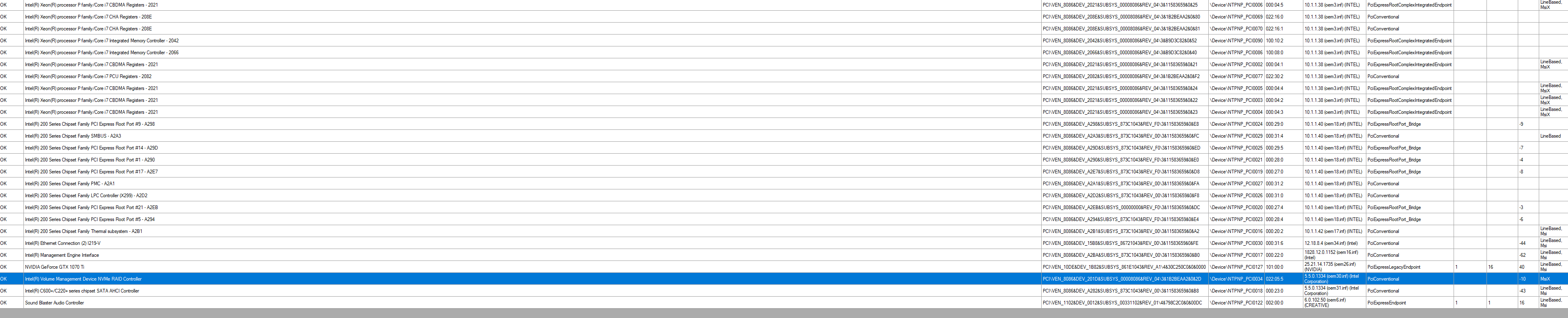
Hi, about the utility to view pci devices I have I highlighted it for you is the device managing the VMD (VROC) Sorry I may have forgotten to tell you that I had a raid 0 of 4 ssd nvme on the hyper X where the OS runs.
About Crystal info the software can’t see the drive , doesn’t show it to me.
About IOU0 could you tell me what exaclty identify IOU0 (IIO PCIe Br1), IOU1 (IIO PCIe Br2), IOU2 (IIO PCIe Br3), MCP0 (IIO PCIe Br4) and MCP1 (IIO PCIe Br4). What is it ? Pcie Slots ? , PCIE lanes from cpu ? I think I’m missing the understanding of that.
(I already tried to change directy on bios with a UEFI tool, but no chance, is why I’m asking what is that) indeed changing some values, it influenced the bandwidth, but not as I would have wished at x16.
I don’t have Graphics card on board, sorry
Did you check the view71.htm ? maybee you can see more about this device.
On CrystalDiskInfo, you did see how to change disk at the top correct? if not, check again, you’ll see “Disk” and there you can select between disks.
It may not work for NVME, VROC, Raid, but I think it should I see mentioned in google when looking around with any of those terms.
Yes, sorry, I eventually noticed it scrolled further off my page on the right, and I’m on 2560 width monitor, not used to having to scroll further over so I didn’t catch that at first No help there though, it doesn’t show what lane is being used. Altough, maybe bus 255 device 05 can help, not sure.
Your question about IOU0 etc is why I was asking you to check this, the only way to know is make a change and check the changes in device manger or other tools that show lane width etc. That’s why I said pick one, we’ll test, or I can change them all if you can use onboard graphics or PCI graphics for a second.
Yes, those are PCIE slots, 1-3 of them have the setting option you wanted. Yes, I looked at view71, nothing helpful there at all for me.
Here is a few threads where users posted some info on figuring that out, but I think he had to make the changes in BIOS per setting and test before he knew which was what slot.
[GUIDE] Adding Bifurcation Support to ASUS X79 UEFI BIOS << See second image and thoughts above, one how to figure out what is what after a change
[Guide] - How to Bifurcate a PCI-E slot << In depth editing, but showing how split slots look in certain apps, and discussion of the IOUx ports/slots - looks like his initial way to figure out is what I mentioned, set them all or one at a time and check.
Maybe best we set one at a time, or make three BIOS with only one changed in each, that way other two left as default in all BIOS, so graphics card will at least work on one slot always. Although, it may still work anyway on a bifurcated slot, just at slower lane speed than it should, not sure.
Do you want me to go ahead and create three BIOS for you, with 4x4x4x4x set one time on each (IOU0, IOOU1, IOU2), but always leaving the other two at default?
The CrystalDiskInfo does not detect the raid drive.
If IOU are the PCIe Slots what are the mpc0 and mpc1 ? on my board i’ve got 4 x PCIe 3.0 x16 (x16, x16/x16, x16/x0/x16/x8, or x16/x8/x8/x8 mode with 44-LANE CPU; x16, x16/x8 orx8/x8/x8 mode with 28-LANE CPU) * + 1 x PCIe 3.0 x4
in the first I have the GC and on the 3rd I have the HyperX
Yes it’s a good Idea , make 3 bios accordingly.
What is the best practice to flash bios ?
Looking for something like this :
https://rog.asus.com/forum/showthread.ph…-Asus-Hyper-M-2
It would be great if we could change the bandwith, check the pics. Wondering maybee if we could have the motherboard block diagram would be easier to understand. but didn’t find anything.
I don’t know what is what on the IOUx, only you can test and find out. The MPC9-1 are not relevant to use, since those do not offer the options you are wanting, so they don’t matter
For Asus BIOS, best way to flash mod BIOS is via USB Flashback. USB Must be formatted to FAT32, all files must be on root of USB, and BIOS file must have special flashback name.
Some USB do not work with flashback, so if you get solid LED or no LED it’s not working (if your USB has LED’s, or same applies to flashback button LED too) Smaller USB usually better, 128MB-2GB best.
When it’s working, the LED will blink several times, then start blinking faster until it’s done, usually a minute or so. I think LED on button either stays solid at end or shuts off, can’t remember.
If LED on button only blinks a few times then solid it’s not working, it must blink many times and then get faster blinks, then you know it’s working.
For the link you mentioned, this is all I see in your BIOS for that section. Looks like it’s been nulled, the info/selection choices blanked and only one slots name is there.
However, later if we find the other stuff we plan to change does not work, I can download that boards BIOS and see what each of those choices should be named in the unnamed slots there, and we can change the default to another value and retest.
As it is now, do you see any of these at Advanced >> Onboard Devices Config? I can unsuppress them for you, looks like you should see the M.2_1 setting, but then the next three will be suppressed.
I am unsure what will happen, if nothing, if broken setup entry (can’t enter BIOS, have to reflash), or if blanked named entry will be shown when no name it on the setting in BIOS (also no names on the setting options either)
This is probably not needed anyway, since your BIOS is by default setup and ready to use VROC. Did you test different drivers, or RST Settings? Is a certain driver required, or certain settings etc, should be some kind of guide out there people have made for these I would imagine.
0x80C6E One Of Option: From CPU, Value (8 bit): 0x0 (default) {09 07 0A 23 10 00 00}
0x80C75 One Of Option: From PCH, Value (8 bit): 0x1 {09 07 0B 23 00 00 01}
0x80C7C End One Of {29 02}
0x80C7E Suppress If {0A 82}
0x80C80 QuestionId: 0xEBD equals value 0x1 {12 06 BD 0E 01 00}
0x80C86 One Of: PCIEX8_4 bandwidth configuration, VarStoreInfo (VarOffset/VarName): 0x1218, VarStore: 0x1, QuestionId: 0xDBB, Size: 1, Min: 0x0, Max 0x1, Step: 0x0 {05 91 0C 23 0D 23 BB 0D 01 00 18 12 10 10 00 01 00}
0x80C97 One Of Option: Auto, Value (8 bit): 0x0 (default) {09 07 06 00 10 00 00}
0x80C9E One Of Option: X8 mode, Value (8 bit): 0x1 {09 07 0E 23 00 00 01}
0x80CA5 End One Of {29 02}
0x80CA7 End If {29 02}
0x80CA9 Suppress If {0A 82}
0x80CAB True {46 02}
0x80CAD One Of: , VarStoreInfo (VarOffset/VarName): 0x1219, VarStore: 0x1, QuestionId: 0xDBC, Size: 1, Min: 0x0, Max 0x3, Step: 0x0 {05 91 02 00 02 00 BC 0D 01 00 19 12 10 10 00 03 00}
0x80CBE One Of Option: , Value (8 bit): 0x0 (default) {09 07 02 00 10 00 00}
0x80CC5 One Of Option: , Value (8 bit): 0x1 {09 07 02 00 00 00 01}
0x80CCC One Of Option: , Value (8 bit): 0x2 {09 07 02 00 00 00 02}
0x80CD3 One Of Option: , Value (8 bit): 0x3 {09 07 02 00 00 00 03}
0x80CDA End One Of {29 02}
0x80CDC One Of: , VarStoreInfo (VarOffset/VarName): 0x121A, VarStore: 0x1, QuestionId: 0xDBD, Size: 1, Min: 0x0, Max 0x2, Step: 0x0 {05 91 02 00 02 00 BD 0D 01 00 1A 12 10 10 00 02 00}
0x80CED One Of Option: , Value (8 bit): 0x0 (default) {09 07 02 00 10 00 00}
0x80CF4 One Of Option: , Value (8 bit): 0x1 {09 07 02 00 00 00 01}
0x80CFB One Of Option: , Value (8 bit): 0x2 {09 07 02 00 00 00 02}
This is what’s in that boards BIOS at these settings. I noticed your board, the similar settings are right above this in CPU storage config instead, which we’ve already been discussing, that has the VROC settings.
The other board doesn’t have this CPU Storage section, since it’s AMD instead of Intel.
0x3F094 One Of Option: Auto, Value (8 bit): 0x0 (default) {09 07 06 00 10 00 00}
0x3F09B One Of Option: GEN 1, Value (8 bit): 0x1 {09 07 02 0D 00 00 01}
0x3F0A2 One Of Option: GEN 2, Value (8 bit): 0x2 {09 07 03 0D 00 00 02}
0x3F0A9 One Of Option: GEN 3, Value (8 bit): 0x3 {09 07 04 0D 00 00 03}
0x3F0B0 End One Of {29 02}
0x3F0B2 One Of: SB PCIE Link Mode, VarStoreInfo (VarOffset/VarName): 0x20B, VarStore: 0x1, QuestionId: 0x25B, Size: 1, Min: 0x0, Max 0x2, Step: 0x0 {05 91 07 0D 08 0D 5B 02 01 00 0B 02 10 10 00 02 00}
0x3F0C3 One Of Option: Auto, Value (8 bit): 0x0 (default) {09 07 06 00 10 00 00}
0x3F0CA One Of Option: GEN 1, Value (8 bit): 0x1 {09 07 02 0D 00 00 01}
0x3F0D1 One Of Option: GEN 2, Value (8 bit): 0x2 {09 07 03 0D 00 00 02}
0x3F0D8 End One Of {29 02}
0x3F0DA Suppress If {0A 82}
0x3F0DC True {46 02}
0x3F0DE One Of: PCIE_X8/X4_4 Bandwidth, VarStoreInfo (VarOffset/VarName): 0x205, VarStore: 0x1, QuestionId: 0x25C, Size: 1, Min: 0x0, Max 0x1, Step: 0x0 {05 91 F4 0C F5 0C 5C 02 01 00 05 02 10 10 00 01 00}
0x3F0EF One Of Option: X8 Mode, Value (8 bit): 0x0 (default) {09 07 F6 0C 10 00 00}
0x3F0F6 One Of Option: X4 Mode, Value (8 bit): 0x1 {09 07 F7 0C 00 00 01}
0x3F0FD End One Of {29 02}
0x3F0FF End If {29 02}
0x3F101 One Of: PCIEX16_1 Bandwidth, VarStoreInfo (VarOffset/VarName): 0x206, VarStore: 0x1, QuestionId: 0x25D, Size: 1, Min: 0x0, Max 0x1, Step: 0x0 {05 91 F8 0C F9 0C 5D 02 01 00 06 02 10 10 00 01 00}
0x3F112 One Of Option: X16 Mode, Value (8 bit): 0x0 (default) {09 07 00 0D 10 00 00}
0x3F119 One Of Option: PCIe RAID Mode, Value (8 bit): 0x1 {09 07 01 0D 00 00 01}
0x3F120 End One Of {29 02}
0x3F122 One Of: PCIEX16_2 Bandwidth, VarStoreInfo (VarOffset/VarName): 0x207, VarStore: 0x1, QuestionId: 0x25E, Size: 1, Min: 0x0, Max 0x1, Step: 0x0 {05 91 FA 0C FB 0C 5E 02 01 00 07 02 10 10 00 01 00}
0x3F133 One Of Option: X8 Mode, Value (8 bit): 0x0 (default) {09 07 F6 0C 10 00 00}
0x3F13A One Of Option: PCIe RAID Mode, Value (8 bit): 0x1 {09 07 01 0D 00 00 01}
0x3F141 End One Of {29 02}
0x3F143 One Of: PCIEX16_3 Bandwidth, VarStoreInfo (VarOffset/VarName): 0x208, VarStore: 0x1, QuestionId: 0x25F, Size: 1, Min: 0x0, Max 0x1, Step: 0x0 {05 91 FC 0C FD 0C 5F 02 01 00 08 02 10 10 00 01 00}
0x3F154 One Of Option: X16 Mode, Value (8 bit): 0x0 (default) {09 07 00 0D 10 00 00}
0x3F15B One Of Option: PCIe RAID Mode, Value (8 bit): 0x1 {09 07 01 0D 00 00 01}
0x3F162 End One Of {29 02}
0x3F164 One Of: PCIEX16_4 Bandwidth, VarStoreInfo (VarOffset/VarName): 0x209, VarStore: 0x1, QuestionId: 0x260, Size: 1, Min: 0x0, Max 0x1, Step: 0x0 {05 91 FE 0C FF 0C 60 02 01 00 09 02 10 10 00 01 00}
0x3F175 One Of Option: X8 Mode, Value (8 bit): 0x0 (default) {09 07 F6 0C 10 00 00}
0x3F17C One Of Option: PCIe RAID Mode, Value (8 bit): 0x1 {09 07 01 0D 00 00 01}
@danielp87 - here is three mod BIOS as we discussed, flash using flashback and do not rename the files
Each BIOS has one of the IOUx changed to x4x4x4x4
BIOS 1 - IOU0 = x4x4x4x4 Default
BIOS 2 - IOU1 = x4x4x4x4 Default
BIOS 3 - IOU2 = x4x4x4x4 Default
http://s000.tinyupload.com/index.php?fil…119907278146666
Thank you I’ll test it and feedback soon.
thank you very much !!!
Could you explain me how you did to modify the settings by default please ?
Thank you.