Recently I have been experimenting with splitting my last unused 8X PCI-E Slot in half. Because I now have a 40 lane cpu and my two GPU’s both take 16X lanes placing a NVME drive on the last slot leaves me with 4X lanes that are wasted. In my case I also have an onboard M.2 connector with an NVME drive but that is connected to the last PCI-E slot and the M.2 Onboard drive is forced to operate through the PCH at lesser performance which is not desirable. Of course I could use the two other PCI-E slots that share bandwidth with my GPU’s but that would mean having them operate at 8X/8X or 8X/16X and despite negligible performance difference was not what I wanted aesthetically. So the solution here is to bifurcate the last slot into x4x4 mode and use a two slot riser adapter.
For many of you with other configurations such as ITX boards this is an invaluable technique. For a lot of you with Asrock boards not a concern since Asrock provides Bifurcation support in their bios’s anyhow. My test board is an MSI Godlike E7883 X99A board with a 6850K. According to the Intel datasheet for this processor bifurcation support is allowable. Wether or not manufacturers provide it is another story. Note I have not yet tested this yet beyond noting the change in HWInfo. Going to have an adapter by weeks end or next week I hope. Here are the steps:
Step 1:
Gather your tools:
MSI UEFI Shell files (google search), RU Bios Utility, AMIBCP 5.02 (version may vary depending on board)
UEFITool ver 21.5, IFR Extractor
Step 2:
Open your Bios in AMIBCP and look for the IntelRCSetup section.
You will note that there are four IIO’s. Your going to have to set all of the IOU2 or whatever IOU # to the desired bifurcation setting. In my case I set IOU2 to x4x4 which maps to my x8 slot. If you’ve got a x16 slot your going to have to find the right IOU 0 or 1 port and set it to x8x8 or whatever you want. Set all of them and save the file with a new name.
Step 3:
Open the original bios file inside UEFITool and search for “IOU1 (IIO PCIe Port 3)” and double click the search result which will bring you to the Platform DXE drive module. From there extract the PE32 body and use IFR Extraction tool tool to extract the String file.
Step 4:
Open the String file in your favorite text editor and search for IOU2 or whatever. Look for each Variable for IOU2 and write down the address. There will be four of these. For example IIO3 IOU2 variable # is ‘0x53C’ and the default value is ‘FF’. To turn on bifurcation of ‘x4x4’ the correct value will be ‘0x0’ or ‘00’. It will look like this:
Form: IIO 3, Form ID: 0x1A7 {01 86 A7 01 7E 04}
0x1CB5B Suppress If: {0A 82}
0x1CB5D Variable 0x211 equals 0x0 {12 06 11 02 00 00}
0x1CB63 Setting: IOU2 (IIO PCIe Port 1), Variable: 0x53C {05 91 BE 04 C7 04 83 02 01 00 3C 05 10 10 00 FF 00}
0x1CB74 Option: x4x4, Value: 0x0 {09 07 CC 04 00 00 00}
0x1CB7B Option: x8, Value: 0x1 {09 07 4F 0A 00 00 01}
0x1CB82 Option: Auto, Value: 0xFF {09 07 76 03 30 00 FF}
0x1CB89 End of Options {29 02}
0x1CB8B Setting: IOU0 (IIO PCIe Port 2), Variable: 0x534 {05 91 C2 04 C7 04 84 02 01 00 34 05 10 10 00 FF 00}
0x1CB9C Option: x4x4x4x4, Value: 0x0 {09 07 C8 04 00 00 00}
0x1CBA3 Option: x4x4x8, Value: 0x1 {09 07 C9 04 00 00 01}
0x1CBAA Option: x8x4x4, Value: 0x2 {09 07 CA 04 00 00 02}
0x1CBB1 Option: x8x8, Value: 0x3 {09 07 CB 04 00 00 03}
0x1CBB8 Option: x16, Value: 0x4 {09 07 50 0A 00 00 04}
0x1CBBF Option: Auto, Value: 0xFF {09 07 76 03 30 00 FF}
0x1CBC6 End of Options {29 02}
0x1CBC8 Setting: IOU1 (IIO PCIe Port 3), Variable: 0x538 {05 91 C6 04 C7 04 85 02 01 00 38 05 10 10 00 FF 00}
0x1CBD9 Option: x4x4x4x4, Value: 0x0 {09 07 C8 04 00 00 00}
0x1CBE0 Option: x4x4x8, Value: 0x1 {09 07 C9 04 00 00 01}
0x1CBE7 Option: x8x4x4, Value: 0x2 {09 07 CA 04 00 00 02}
0x1CBEE Option: x8x8, Value: 0x3 {09 07 CB 04 00 00 03}
0x1CBF5 Option: x16, Value: 0x4 {09 07 50 0A 00 00 04}
0x1CBFC Option: Auto, Value: 0xFF {09 07 76 03 30 00 FF}
Step 5:
Format a fat32 usb key and copy the msi uefi shell files (or any shell file belonging to edk toolkit) to ‘EFI/BOOT’ folder. The name of the Shell executable usually is BootX64.efi. Download the RU Utility and copy it to another folder call it ‘EFI/RU’. Insert the USB key and reboot the intended machine from the USB key and when your shell loads up hit any key to go to the command prompt. Bypass or delete any auto config Nsh file that MSI may have included.
Type Map -r -b and look which FS# is your usb key. Mine was FSa so typeing FSA: enter took me to my usb key and I cd’d into my RU folder and ran the RU efi utility.
Step 6:
When inside RU hit [ALT]+[+=] keys at once to search for ‘IntelSetup’ file and press enter to load up its strings. From there you’ll see a bunch of addresses which correspond to the Variable names such that ‘x53C’ variable is actually an address. You can scroll down by hitting [CTRL]+[PGDN] keys and use arrow keys to find individual entries. In my case all my IOU2’s corresponded to x539, 53A, 53B, + x53C which all had values of ‘FF’ that I set to ‘00’. Your going to want to change those to ‘00’ to enable ‘x4x4’. Just don’t set all of them if you don’t have to. Setting all of them demotes the link speed to 2X speeds. I found setting x539 to ‘00’ was enough though more experimentation may be needed. If your trying to mod a 16x slot you will obviously want to search for IOU0 or 1 and set them to ‘30’. From there [CTRL]+[W] writes it to ram and I think [ALT]+[Q] exits the program.
RU looks like this:
Step 7:
After exiting reboot the computer. Go into HWinfo and look at the lane distribution. You should have now a split bus. This of course is not permanent and a cmos reset will probably wipe this but its good for testing purposes before you flash your modded bios file you made earlier.
Finished result. Note that the second IIO - PCI Express Root Port #1 has been split in half:
Again I stress this has not been tested in the field to see if it works physically yet!!!
Note:
If IFR Extractor fails to read the file ‘Extract as is’ instead.
Use at your own risk.
Extra points to anyone if you could find a setting to turn on the M.2 and PCI-E #5 ports on simultaneously!
I just wanted to report my successful bifurcation of the PCI-E 8X Slot into two PCI-E X4 buses! I used a Supermicro RSC-R2UU-2E4R 2U PCIE 8X to 4X4X adapter and now I am using both slot and M.2 onboard connection at full 4X PCI-E bandwidth!! 

Having a little issue with the Current link speed sometimes showing up at 2.5 GT/S instead of 8.0 GT/S for the Lite-On NVME drive. The only solution I have found is to reset the bios settings, reboot, then re-enable my bifurcation setting and sometimes that works.
Not sure if its my Riser card or cable at fault. Perhaps if @lordkag or @CodeRush could provide some assitance. Not sure what is going on except that the latency values differ greatly from one drive to the next and I think thats related.
Thank you.
Well I ran some more tests and it seems that a side effect of bifurcating the PCI-E 8X lane in two is that the Plextor occasionally sets itself to 2.5 GT/S mode. It doesn’t happen when the bios hack is turned off and its not related to the riser cable. I mean it will happen when the Plextor card is plugged in directly into the pci-e slot and goes away if I undo the mod. Interestingly enough the other NVME drive, the Samsung 950 Pro on the other end of the 4X switch, doesn’t behave this way. So I think its something to do with the required latencies of the drive possibly the Payload side required. At the moment I am experimenting with Setpci windows port setting the x80 retraining bit on to see if I can get the card to reinitialize at 8.0 gt/s when it throttles down to 2.5. However I can always get it to 8.0 GT/S by reinstalling NVME drivers so at the very least there is a software solution somewhere. I can imagine creating a script to run before shutting down or rebooting to reset the pci-e variables so at every boot I get 8.0 GT/s. Rather like to figure out what needs to be set in bios. Bet its latency values.
Still haven’t figured this out yet but for those that may be curious I have figured out how to change the Link Speed settings on the fly using SETPCI (linux windows port). With these commands I can set the link speed from 8.0 to 2.5 or 5.0 GT/S and back again. However when it faults at 2.5 GT/s at boot I could only get it up to 5.0 GT/S. I have a theory though what is going on in that much like an overclock the 8X IIO controller sometimes has stability issues just like when you don’t have enough voltage on an overclock. So now it has two manage two buses or link paths and sometimes it faults. In anycase these are the SETPCI Commands to change link speed on the fly:
2
3
4
5
setpci -v -s 00:01.0 C0.b=0x03
setpci -v -s 00:01.0 254.b=0x01
setpci -v -s 00:01.0 A0.w=0x0020:0x0020
For 8.0 GT/S C0 needs to be 0x03
For 5.0 speed C0 needs to be set at 0x02
For 2.5 speed C0 set it at 0x01
The 00:01.0 is the Intel IIO controller for that first 8X PCI-E controller. The address may vary. Need to use LSPCI, SIV, or HWInfo to
identify the correct controller.
A0 is the LNKCON 1, C0 LNKCON2, and x254 is LNKCON3 which sets the Re-Equilibrate bit on but not sure if it does anything..
Hello!this is work on Asus Rampage V Extreme X99? he has boosting on my SLI cards or not?
Only one way to find out. May work. Not sure.
Just wanted to add a couple tips to this guide as far increasing the chance of success as it isn’t just enough to turn on bifurcation by setting the port to x4x4. It still may not work or sync properly or need more time to sync so there are a few settings you can try changing.
1. Extended sync mode : turn on
2. Link Retraining retry : set to max
3. Link Training Timeout: change from a 1000 to 10000 (in hex would be 2710 or 1027 in proper reverse order at offset x26E)
Example:
2
3
4
5
6
7
8
9
10
11
12
13
14
15
16
17
18
19
20
21
22
Variable 0x3A2 equals 0x1 {12 06 A2 03 01 00}
0x3B1A4 			Setting: Extended Synch, Variable: 0x26C {05 91 CD 05 CE 05 33 03 01 00 6C 02 10 10 00 01 00}
0x3B1B5 				Option: Disabled, Value: 0x0 {09 07 04 00 30 00 00}
0x3B1BC 				Option: Enabled, Value: 0x1 {09 07 03 00 00 00 01}
0x3B1C3 			End of Options {29 02}
0x3B1C5 		End If {29 02}
0x3B1C7 		Subtitle:  {02 87 02 00 00 00 00}
0x3B1CE 		End {29 02}
0x3B1D0 		Grayout If: {19 82}
0x3B1D2 			Variable 0x3A2 equals 0x1 {12 06 A2 03 01 00}
0x3B1D8 			Setting: Link Training Retry, Variable: 0x26D {05 91 F9 05 FA 05 34 03 01 00 6D 02 10 10 00 05 00}
0x3B1E9 				Option: Disabled, Value: 0x0 {09 07 04 00 00 00 00}
0x3B1F0 				Option: 2, Value: 0x2 {09 07 D6 05 00 00 02}
0x3B1F7 				Option: 3, Value: 0x3 {09 07 D7 05 00 00 03}
0x3B1FE 				Option: 5, Value: 0x5 {09 07 D9 05 30 00 05}
0x3B205 			End of Options {29 02}
0x3B207 		End If {29 02}
0x3B209 		Grayout If: {19 82}
0x3B20B 			Variable 0x3A2 equals 0x1 {12 06 A2 03 01 00}
0x3B211 			Numeric: Link Training Timeout (uS) (2056-2056) , Variable: 0x26E {07 94 FB 05 FC 05 35 03 01 00 6E 02 10 11 0A 00 10 27 0A 00}
0x3B225 				Default: 16 Bit, Value: 0x3E8 {5B 07 00 00 01 E8 03}
I myself have Extended Sync off globally but enabled directly on the bifurcated port inside IntelSetup.
Hello,
I’m trying to bifurcate PCIe on asus z97-a to x8x4x4 but can’t find any hidden settings that can manage this in amibcp…
Extracted setup ifr also do not have any bifurcation settings.
I wonder is it possible to add such functionality myself or may be manage this throght cpu configuration pins?
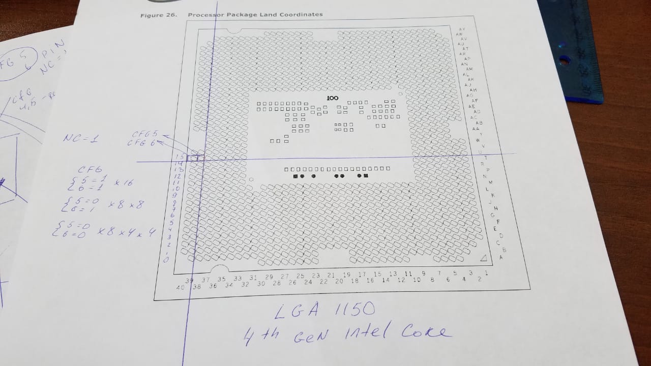
for example I can connect cfg5, cfg6 to each other and then isolate cfg6. so it will be x16 or x8x4x4 when mb trying to set x8x8.
Hi,
I’m wondering is it possible to change bifurcation from x8x8 to 8x4x4 if there is no such settings in UEFI variables, but bios changing it between x16 or x8x8 automatically if slot not empty .
I’m not found intelRCsetup, IOU, IIO or something like this in asus z97-a bios, but option for changing pcie version 1,2,3 each slot.
thru hardware cfg5,cfg6 it don’t work.
I am not sure if bitfurcation is possible on socket 1150/1151[…] systems at all?
As I suspect this is a feature which is available or possible on systems which are related to the corporate segment, like the socket 2011/2066 systems.
The "enthusiast paltforms" like X79, X99[…] are related to the corporate platforms C602, C612[…] which support bitfurcation by default.
And for Socket 2066/X299 Intel decided to make this option officially available to the domestic "enthusiast platform" also, like AMD did for X299.
All I know for sure the CPU and chipset z97 support bifurcation x16 to x8x4x4 and x8x8. And some vendors like Asrock have this option in the bios.

Hi, actually I can’t. But here is the link where is I read this about Asrock:
https://hardforum.com/threads/pcie-bifur…post-1041787472
https://www.bios-mods.com/forum/Thread-M…k-Voltage-Limit
For example z97 MSI Gamming 5,7 have 3 pci-e 3.0 slots that support automatic bifurcation:https://us.msi.com/Motherboard/Z97-GAMING-7/Specification
But I think not via manual settings in bios but upon initialisation thru requesting each slot card presence pin.
Hi,
Sorry to join in late but as far as weather it will work or not depends on firstly if there are variables that can be set in the firmware. This is usually accomplished using a bios variable IFR extractor or using AMIBCP to look around. If there are no such variables we have to look into the whitepaper documentation on the processor and find if there are any registers that control this for the particular processor, and then hope we find a bios variable that sets it or manually set that register using RU.EXE from an efi shell or other utility that does this. The downside is that you’ll never be able to reset your cmos without not losing the changes.
Thats just a generalization but it could be doable. Need more specifics.
@crucifier - thanks, I will check them out. Manually being able to change doesn’t need to be possible for user, but actually having the setting within the BIOS (Hidden) is a must, so I only wanted to see how/where it’s implemented
Well got to look into the technical whitepapers and hope theres a variable that can be turned on and grafted into setup otherwise without the ability to machine code it won’t be possible as far as I am concerned.
Yes, I agree, but if there’s not even BIOS setting hidden then we know it’s probably not possible or at very least will be difficult to add/enabled
@crucifier - bios-mods link does not show anything, only user asking Asrock and them giving generic response (of no actual response indicating anything is enabled/possible)
[H] forum thread makes it sound like per the chipset specs this is possible at that level, nothing else Asrock specific except them “Not” implementing it. So seems like you haven’t linked anything showing this is enabled on any Asrock board, more-so the opposite I think
I’ll check MSI BIOS shortly - nothing visible or hidden for lane width or bifurcation in MSI Z97 Gaming 7
If we can uncover what register controls this bet you can do it via the command line and make a batch file
hello, thank you for join the discussion
Asrock users telling about bifurcation support in beta BIOS, but I checked beta BIOS section for some boards inside BCP and still no hidden settings in it.
Asus z97-a mobo sets bifurcation configuration automatically between x16 and x8x8 if second x16 pci-e slot has card installed. And I’m wasted 4 pcie lanes for using it for second NVME disk.
As it doing automatically I think there is no possibility to set controll register statically it will be overwrited during POST. But if it possible to mod BIOS to set x8x4x4 instead of x8x8 it can solve my problem.
The z97 chipset documentation link:
https://www.intel.com/content/www/us/en/…-datasheet.html
CPU Haswell documentation:
https://www.intel.com/content/dam/www/pu…1-datasheet.pdf
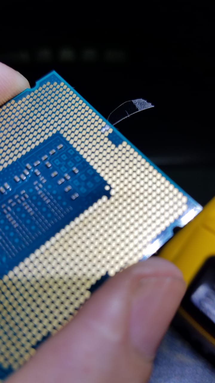
CPU documentation in secion 6.3. tells that CFG[6:5]: controls PCI Express* Bifurcation. This is physicall pins on socket which should be set to 1/0.
[Guide] - How to Bifurcate a PCI-E slot
I’m already experimented with it, but no luck. Nothing changed in hwinfo. May be it can’t be done this way, maybe I didn’t do it very well.