I’m sharing some extra research info that I couldn’t find in the existing bifurcation guides. I collected pieces of various info from all over the place until it started coming all together and making some sense to me. Hopefully this helps someone.
Q: What is IIO?
A: Integrated Input/Output controllers manage traffic between PCI Express and CPU domains.
Q: Why do I see IIO0, IIO1, IIO3 and IIO4 in AMIBCP? Do I need to configure bifurcation on all four IIO?
A: BIOS has four IIO entries because some motherboards may have up to 4CPUs. That’s right - each IIO corresponds to its own CPU:
CPU0=IIO0
CPU1=IIO1
CPU2=IIO2
CPU3=IIO3
Note: Some BIOSes start IIO enumeration at IIO1,… so adjust accordingly i.e. first CPU would correspond to the first IIO# from the list and so on.
With that in mind, you should NOT set bifurcation on each IIO. Instead, you need to identify the proper IIO and IOU Port that corresponds to your PCIe slot of choice.
Q: How do I identify the correct IIO and IOU for my slot?
A: First and foremost you need to find the block diagram for your motherboard. I’ll use mine as an example below.
Gigabyte MD70-HB0
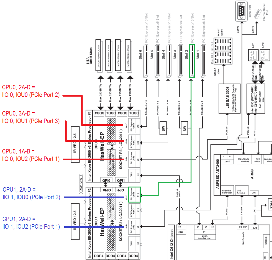
Note CPU0 and CPU1 and how Ports 1A-B, 2A-D, 3A-D on the CPUs are mapped to physical PCIe slots
For instance, Port 2A-D on CPU0 corresponds to physical Slot 6 (x16), the top PCIe slot on my motherboard where I have my GPU plugged in.
While Port 2A-D on CPU1 corresponds to Slot 2 (x16) that can share half the lanes with Slot 3 (if populated).
FYI A-D means four x4 paths that make up a total of x16 lanes. Likewise A-B means two x4 paths, which is x8 in total.
So I wanted to bifurcate Slot 2 (x16), marked in green, which corresponded to “Port 2A-D” aka “IOU0 (PCIe Port2)” on CPU1. Now if I were to change IOU0 settings on all IIOs, then I would have messed up my GPU Slot 6, because it’s also IOU0.
To avoid that I changed IOU0 values on IIO1 ONLY. Did NOT touch IIO0.
First try - SUCCESS. To confirm my theory, with the new settings in place, I removed the GPU and plugged my 4xNVMe card into GPU Slot 6 - bifurcation did not work there, only 1 out of 4 NVMe drives was visible, meaning that only the desired PCIe Slot 2 was affected!
I followed this guide to make the changes: [Guide] - How to Bifurcate a PCI-E slot by @davidm71
==========
Question that I am yet to answer:
What happens if I am running a single CPU configuration on this 2-socket mobo? Do I still make the changes under IIO1 > IOU0 (Port2) even though Socket#2 is empty? Perhaps IIOs are bound to Sockets after all, not CPUs? So that the single CPU0 manages its own PCIe slots plus the slots from the unpopulated neighbor Socket#2 over QPI links?
Any comments and corrections are greatly appreciated!
This is the spirit of experimentation and research I totally applaud you for sharing with us all. Please continue on and let us know how it goes. Would like to know what motherboard you were using and what kind of NVME card? I personally used a Supermicro bifurcated card and plugged in my cards using riser cables. Much appreciate your findings to the cause…
Thanks
Thanks for the kind words and the initial work that sparked my interest and motivated me to keep digging! It’s nothing really, but it just feels good giving back to the community and bringing value to the forum, even as little as this.
My motherboard is Gigabyte MD70-HB0
Expansion card is ASUS Hyper M.2 x16 PCIe 3.0 V2
NVMe drives: two WD Blue SN570 1TB, one Samsung 970 Evo 500GB and one ADATA XPG SX8200 Pro 256GB
I will be keeping WD Blues in the card and buying 2 more eventually. I just populated all the slots to confirm I was seeing all 4 and bifurcation worked correctly.
As for performance, I am running UNRAID on the server, so measuring drive speeds and overall card throughput is not as intuitive and trivial as in Windows/Linux considering the plethora of tools readily available for these OSes.
I am also new to UNRAID, so I am just learning. Or… maybe I should just boot a Linux LiveCD and take the measurements…? Hm… 
Not familiar with UNRAID. Probably a liveCD or a secondary OS install on a spare SSD be a good idea.
Was wondering if any one has a copy of the Intel Datasheet for the Broadwell-E X99A platform. Looking to find registers to manipulate to force a pci-e x16 slot to operate at x8 such that hopefully my m.2 will have the lanes it needs to bump up from pch x2 operation to full pci-e x4 operation when all the pci-e slots are occupied with solid state drives for example.
Thanks
Thank you for the reference. After studying the specifications there are I think a couple ways to do this. One you can alter the link capability register for the appropriate bus and set it from x16 to x8 and hope that the motherboard would allocate the extra x8 lanes to the last slot but after studying the motherboard lane schematics I don’t think this is possible physically. Thats because as long as the last slot is occupied it forces the M.2 it shares lanes with into PCH x2 operation. As it is right now this is my current configuration:
GPU: Slot 1, Slot 2 NA, Slot 3 NA, Slot 4 (x8 raid card), Slot 5 x4 M.2 adapter card, Onboard M.2 X4 Stick (forced to run at X2 via PCH).
When I look at the manual for the MSI X99a Godlike it really doesn’t explicitly tell you what would happen if Slot 3 and Slot 4 were both occupied but I can guess considering that if Slot 2 is occupied Slot 1 + 2 are switched into x8 operation. So I would guess that the same is going to happen if Slot 3 + 4 are occupied leaving Slot 5 empty. That should open up the onboard to full x4 PCIE operation.
Hopefully.