Unlocking FD on Dell Vostro 3670

Hello world!

I’m currently having problem modding my ‘BIOS’ (actually the firmware, specifically disabling ME) when I’m trying to unlock the BIOS chip.
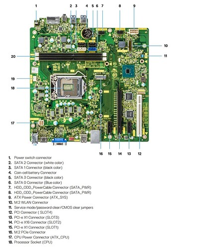
I have already set the “Service mode” jumper (it only unlocks the BIOS part) and setting the UEFI variable “Me FW Image Re-Flash” to 0x01, but it doesn’t seem to be sticky and always reset back when I rebooted my computer. According to many guides on GitHub, there maybe also another UEFI variable I have to set in order to make the changes preserved after reboot.
So, how to fully unlock the firmware?

BIOS dump: https://send.vis.ee/download/8f018fcfa6691075/#65AQ6npEtLD7ouleuGLqZQ (I’m unable to upload file directly)(dumped and verified using FTP in edk2 UEFI shell)

Try modifying the ME FW straps with FIT12 regarding regions access.

Did you mean Flash Image Tool from CSME System Tools v12?

Well I just tried it, and it bricked my PC (also I don’t have an external programmer :upside_down_face:)

Well seems that now you need to undo your actions… and most likely you’ll need one.
Welcome to mod world… where users are free to take the risks or not.

1 Like

Would any SPI flasher would work, or it depends on what chip my computer have?

That’s the whole point why I’m risking myself, to enrich my skill and knowledge…


I’m still wondering how could I flash the FD while it still locked and why only changing the region permission (checked using a hex editor) would brick my computer so easily? Are there any other way to unlock the chip?

A simple cheap CH341A for shorth use period will probably do, start looking for the ICs on the board, available space around ICs to connect it or SPI headers etc, reading other Dell recoveries threads, CH341A guides on the forum, PDFs of the visually identified ICs…
For a user that never made this… patient user is needed and a lot of reading, its a user task only.

I don’t know what actions you took, what data you flashed and how was flashed…really don’t care none of this now…bricked is bricked. A side note…FPT writes whatever we give him, right or wrong… but can only write if the regions allow it (FD)
Besides FD these OEM bios (DELL, HP, LENOVO…) have specific security bits, TPM etc…
There’s also jumpers for several factory actions… as ME override etc…
You have a lot to read now, good luck.

@666, did you ever work this out? I ran into the exact same problem. I’m not really understanding why the FPT flashed it in the first place, but it did, but not correctly. I may have figured it out after beating my head up against a wall. Here is the result of the FPT “good” flash after a 2nd attempt (which should have stopped me dead in my tracks):

FPTW64.exe -f bios.bin

Reading HSFSTS register… Flash Descriptor: Valid

--- Flash Devices Found ---
ID:0xEF4019    Size: 32768KB (262144Kb)

Error 167: Protected Range Registers are currently set by BIOS, preventing flash access.

FPTW64.exe -f bios.bin

Reading HSFSTS register… Flash Descriptor: Valid

--- Flash Devices Found ---
ID:0xEF4019    Size: 32768KB (262144Kb)

GbE Region does not exist.

Processing Flash memory block 38 from 8191.

  • Erasing Flash Block [0x027000] - 100 percent complete.
  • Programming Flash [0x0027000] 16KB of 16KB - 100 percent complete.
    Processing Flash memory block 42 from 8191.
  • Erasing Flash Block [0x02B000] - 100 percent complete.
  • Programming Flash [0x002B000] 8KB of 8KB - 100 percent complete.
    Processing Flash memory block 45 from 8191.
  • Erasing Flash Block [0x02E000] - 100 percent complete.
  • Programming Flash [0x002E000] 4KB of 4KB - 100 percent complete.
    Processing Flash memory block 5633 from 8191.
  • Erasing Flash Block [0x1602000] - 100 percent complete.
  • Programming Flash [0x1602000] 8KB of 8KB - 100 percent complete.
    Processing Flash memory block 5641 from 8191.
  • Erasing Flash Block [0x160A000] - 100 percent complete.
  • Programming Flash [0x160A000] 12KB of 12KB - 100 percent complete.
    Processing Flash memory block 5696 from 8191.
  • Erasing Flash Block [0x1641000] - 100 percent complete.
  • Programming Flash [0x1641000] 200KB of 200KB - 100 percent complete.
    Processing Flash memory block 5752 from 8191.
  • Erasing Flash Block [0x1679000] - 100 percent complete.
  • Programming Flash [0x1679000] 4KB of 4KB - 100 percent complete.
    Processing Flash memory block 5759 from 8191.
  • Erasing Flash Block [0x1680000] - 100 percent complete.
  • Programming Flash [0x1680000] 24KB of 24KB - 100 percent complete.
    Processing Flash memory block 5761 from 8191.
  • Erasing Flash Block [0x1682000] - 100 percent complete.
  • Programming Flash [0x1682000] 4KB of 4KB - 100 percent complete.
    Processing Flash memory block 5763 from 8191.
  • Erasing Flash Block [0x1684000] - 100 percent complete.
  • Programming Flash [0x1684000] 4KB of 4KB - 100 percent complete.
    Processing Flash memory block 5765 from 8191.
  • Erasing Flash Block [0x1686000] - 100 percent complete.
  • Programming Flash [0x1686000] 4KB of 4KB - 100 percent complete.
    Processing Flash memory block 7073 from 8191.
  • Erasing Flash Block [0x1BA2000] - 100 percent complete.
  • Programming Flash [0x1BA2000] 4836KB of 4836KB - 100 percent complete.
    Processing Flash memory block 7620 from 8191.
  • Erasing Flash Block [0x1DC5000] - 100 percent complete.
  • Programming Flash [0x1DC5000] 468KB of 468KB - 100 percent complete.
    Processing Flash memory block 7655 from 8191.
  • Erasing Flash Block [0x1DE8000] - 100 percent complete.
  • Programming Flash [0x1DE8000] 116KB of 116KB - 100 percent complete.
    Processing Flash memory block 7920 from 8191.
  • Erasing Flash Block [0x1EF1000] - 100 percent complete.
  • Programming Flash [0x1EF1000] 16KB of 16KB - 100 percent complete.
  • Processed memory blocks 8191 from 8191.
    RESULT: The data is identical.32768KB of 32768KB - 100 percent complete.

Flash device was programmed. It is recommended to perform
G3 power cycle to complete the flashing process.

FPT Operation Successful.

The FPT modified flashing the first 3 blocks. For the 1st block, it erased [0x027000] and wrote [0x0027000]. That has to be it.

You’ll have to attempt to correct this by using a CH341A flasher with a 300mil SOP16 to dip8 Flash CHIP IC Test Clips BIOS Programmer Socket Adapter SOP SOIC SOIC16 Converter for 25 SPI Flash 25series. Like this one.

@MeatWar, can this be corrected with a HEX editor? I just recognized this, and my flash attempts have been obviously coming up short.

https://www.badcaps.net/forum/troubleshooting-hardware-devices-and-electronics-theory/troubleshooting-desktop-motherboards-graphics-cards-and-pc-peripherals/bios-schematic-requests/102511-dell-vostro-3670-18457-1-need

[EDIT: removed inherently broken bios - see posts below]

The attached is the UBU RAID, Realtek LAN, Intel GOP and video, and microcode modified “Name2” bios.

Word to the wise. If it’s a fairly modern Dell, just use a CH341A flasher. It should leave you with a solid BIOS you can work with. The Intel Flash Programing Tool (FPT) may give you headaches, if you can properly dump a full BIOS to begin with. I got lucky.

This computer has a service mode jumper. It’s possible that I FPT mis-flashed this placing the physical jumper into service mode, because I couldn’t dump a full bios with the wrong pin placement, after the CH341A flash.

Weirdly, the UBU mods didn’t stick, and I’m not exactly sure why. The only thing I can think of is that there was enough in the badcaps forum bios to post, and then draw from a backup on the OS SSD.

No matter what I use (FPT or CH341A), I cannot get the UBU modified bios system to post, and I’m not getting why when using the CH341A. For now, I have to use the (older) badcap bios’. This 2nd time to unbrick, I used the “stock” Dell Vostro 3670 (V_2.26) (Name1).bin.

Go here for the outstanding issue of using UBU to modify and flash the Winbond W25Q256JV 32MB bios chip on these Dells.

SoniX

The bios is new, the sizes are 32, and the problems are old - there is no free space in the volumes.

Potential solution in this thread. Maybe, maybe not.

Edit: BTW, there’s no issue with flashing with the Intel ME Flash Programming Tool (FPT). It’s a fundamental problem with volumes space. If you UBU modify the bios and flash with a programmer, you’ll get the same result.

A post was merged into an existing topic: [Discussion] UBU Tool related Questions, Reports and Suggestions

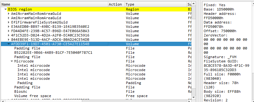
This modern bios volumes space issue has been an issue for a long time. You will not be able to replace microcodes with UBU. You’ll have to get down and dirty with a hex editor. That non-empty Padding file under File GUID: B52282EE-9B66-44B9-B1CF-7E5040F787C1 needs to be maintained.

Even though UBU (MMT 5.2.0.24 or UEFIReplace v0.25.0) can’t properly deal with the no free volume space, there is plenty of FF room in the Padding after the last microcode. FF’s were removed there to maintain proper size after accommodating the new, larger microcodes.

I’m away from this computer until Sept 10, so I can’t test it for a while, but I’m pretty confident that I got it right.

[EDIT - FIT Table broken BIOS removed - see posts below]

The attached is the full bios after hex work that only deals with updating microcodes. As you’ll see in the text file, I did run the bios through UBU to update other stuff. But given the overall UBU volumes space limitation issue, a UBU “other items” modified bios may still present problems. The other mods did present size changes. I may or may not bother with flashing beyond updated microcodes. It’s not easy physically flashing with the 16 pin clip if updated other items break the bios.

I’ll follow up. If this works, it will probably be possible to FPT flash the ucode with fptw64 -a 0x1D50000 -l 0xF0000 -f ucode.bin once you’re up and running with the original bios fix and updated 2.33 from Dell. Of course, that won’t be necessary if my attached bios is good, and you’re physically flashing a bricked box.

Reading through the UBU thread from 2019 and looking more closely for errors, I think I found a big one on the posted bios with a closer look at the UEFITool output:

My hex editor work looks to have broken the FIT table. Back to the drawing board.

SoniX worked his magic on the UEFI BIOS Updater (UBU) v1.80.a16, and the script now enables the user to include/maintain the Padding file under File GUID: B52282EE-9B66-44B9-B1CF-7E5040F787C1 for these modern bios’ that require it.

For proper microcode updating, it doesn’t matter whether you choose 0 - Do not use MMTool. (As in UBU v1.7x) or 1 - Use MMTool. (If, after replacement without MMTool, XMP, OC, etc. do not work,) at first script run.

What matters when updating microcodes is selecting A - Start replacement Alternative with MMTool. This critical selection will maintain the needed Padding file.

Whether you choose to use MMTool at the beginning or not, MMTool (mmtool_a5.exe/5.2.0.24, in my case) must be in the UBU folder.

Thanks again to SoniX for his awesome tool and work! I won’t be able to test this for a while, but his work looks perfect, and he saved me from additional hex editor work to correct my FIT table breakage.

I’m editing the post 2 above this to remove the FIT table broken bios. The clean, unmodified bios can be found here.

Had to finish off the FIT Table fix with a hex editor just to learn. Great guidance, although I came at it from a slightly different angle. I was off by 3 FIT Table hex values - easily corrected by reversing microcode addresses in UEFITool NE and hex editor inserting them/overwriting bad values under the FIT table offsets.

My manually created and corrected bios exactly matches what was produced by UBU.

Again, based on this discussion, I’m going to FPT flash the attached ucode.bin with: fptw64 -a 0x1D50000 -l 0xF0000 -f ucode.bin, and then maybe flash the full bios with “other updates” that was created by UBU - feeling good about that now.

The attached is the updated ucode.bin. The Volume_FFSv2_AFDD39F1-19D7-4501-A730-CE5A27E1154B.vol file is the same thing Extracted as is … by UEFITool.

Thanks again to SoniX. I’ll follow up.

ucode bin.zip (974.8 KB)