Unlock Intel Flash Descriptor Read/Write
Access Permissions for SPI Servicing
Last Updated: 2018-03-20
This guide is relevant to those who need to understand what the Intel Flash Descriptor is, how its SPI Region Read/Write Access Permissions work, how to check its Locked/Unlocked status and what methods are available to unlock it for system firmware repair and/or updating. In this guide, the term "system" means an individual user machine whereas "model" refers to all those "systems" released by the OEM/ODM.
A. About Intel Flash Descriptor
Every system stores its firmware at one or more SPI chips. The SPI firmware image of Intel based systems consists of various regions such as Flash Descriptor, (Management/Trusted Execution) Engine, Gigabit Ethernet, BIOS/UEFI and so on. Although the SPI image can be commonly referred to as "BIOS" or "UEFI", it is very important to note that it is not technically the same, as the BIOS/UEFI is only one of its regions. This guide will focus on its first region, the Flash Descriptor.
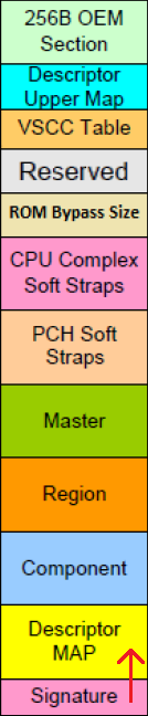
The Intel Flash Descriptor (FD) is a data structure that is programmed on the SPI flash chip on all Intel based platforms. It contains information such as space allocated for each region of the flash image, read-write permissions for each region, reserved space for vendor-specific data, chipset configuration parameters and more. The fixed size of the Flash Descriptor is 4 KB (0x1000) and, depending on platform generation, roughly consists of these sections:
- Header: Consists of a 0x16 sized Reset Vector and a 0x4 sized Signature tag 0x5AA5F00F.
- Map: Pointers to all the descriptor sections as well as the size of each.
- Component: Information about the number & density of all components, read, write and erase frequencies as well as invalid instructions.
- Region: Defines the offsets & sizes of all available regions which are Flash Descriptor (FD), BIOS, Management Engine (Engine), Gigabit Ethernet (GbE), Platform Data (PDR), Device Expansion 1, Secondary BIOS, CPU Microcode, Embedded Controller (EC), Device Expansion 2, Innovation Engine, 10 Gigabit Ethernet 1, 10 Gigabit Ethernet 2, Reserved 1, Reserved 2 and Platform Trust Technology (PTT).
- Master: Contains the hardware security settings for the flash, granting read/write permissions for each region and identifying each master.
- Chipset Soft Strap: Contains PCH/SoC configurable parameters.
- CPU Complex Soft Strap: Contains Processor configurable parameters.
- ROM-Bypass Size: Stores the Engine firmware regions’ debug partition size.
- Reserved: For future use or FD revisions.
- VSCC Table: Holds the JEDEC ID and the Engine VSCC information for all the SPI Flash chip(s) supported by the SPI image.
- Upper Map: Determines the length and base address of the Engine VSCC Table.
- OEM Section: Reserved for use by the OEM/ODM and 0x100 in size.
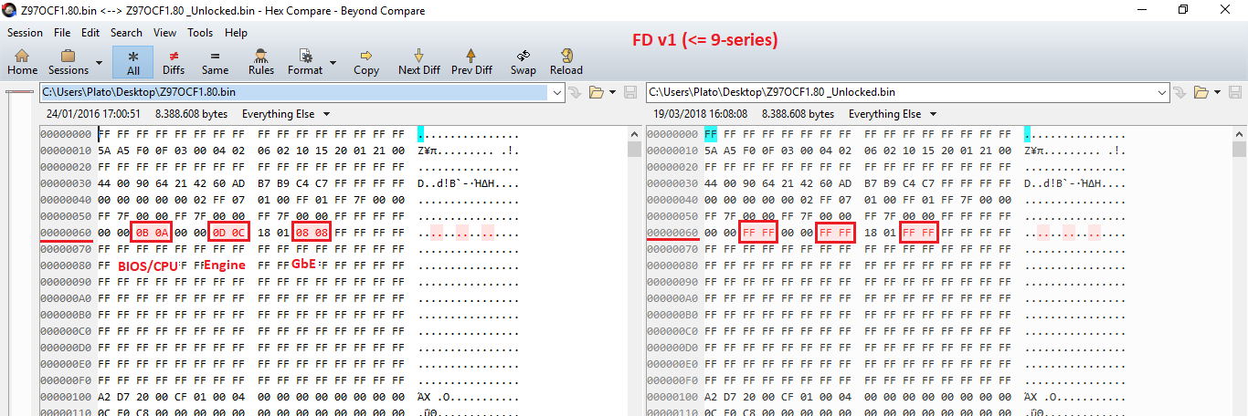
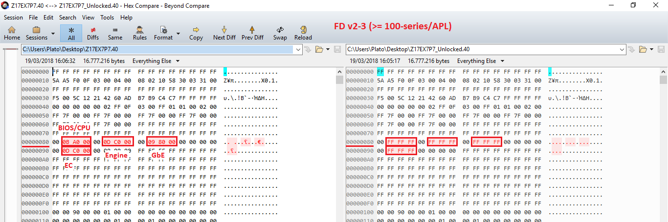
Older platforms used the (community-named) Flash Descriptor v1 which, among others differences, could support up to 8 SPI regions. More modern platforms (>= 100-series or APL) utilize Flash Descriptor v2-3 which can support up to 16 SPI regions.
B. Read/Write Access Permissions
The Flash Descriptor Region Read & Write Access Permissions are found at its Master section. Each FD Permission Access Entry is 0x4 sized and in Little Endian order (each byte read from right to left). At FD v1/v2 Entries, only the first two/three bytes are used respectively, with the rest remaining unused. The first value is the Write access and the second is the Read access. Each Read and/or Write bit signifies that particular partitions’ access to the other ones. Take for example a hypothetical FD v1 region "E" which has these Read/Write permissions to the other 7 regions:

In bits, "Yes" is signified by 1 and "No" as 0. So, region Es’ Write equals to 10101100 = 0xAC whereas Es’ Read equals to 10111111 = 0xBF. Since Write proceeds Read value and only the first two bytes are used at FD v1, the final Access Permissions Entry for the hypothetical Region E is 0xACBF0000.
Thus, if you want to enable full & unsecured read/write access at the Flash Descriptor for all important regions (CPU/BIOS, Engine, GbE, EC), you must set them to 0xFF for FD v1 or 0xFFF for FD v2-3 as follows:
C. Security vs Serviceability
The information stored in the Flash Descriptor can normally only be written during the manufacturing process as its read/write permissions should be set to Read only when the system leaves the factory. That is the Intel recommended practice to improve the platforms’ security by not allowing remote or OS-based attacks to the systems’ SPI firmware. However, that does not allow to repair the SPI firmware via software solutions in case something is wrong. This guide will focus on how to unlock the Flash Descriptor in order to temporarily allow read/write access to its regions.
When it comes to the most important SPI image regions (FD, GbE, Engine & BIOS/UEFI), the Flash Descriptor read/write access permissions recommendation by Intel is to always keep the Flash Descriptor itself, the Gigabit Ethernet as well as Engine CS(ME)/CS(TXE)/CS(SPS) firmware locked, for security purposes. Notice that BIOS/UEFI is not locked by the Flash Descriptor and thus OEMs are responsible for implementing BIOS-specific read/write restrictions such as Protected Range Registers and so on. That means that the Flash Descriptor is not responsible for any read/write restrictions set at the BIOS/UEFI region of the SPI chip, so the FD-related methods below will not be of any assistance in such cases.
It is worth noting that users who want to service or manually update their system firmware, must pay attention to not accidentally lock an already unlocked Flash Descriptor when updating or re-flashing the SPI/BIOS image either manually or from the official OEM/ODM package. If your FD is unlocked and you flash a SPI/BIOS update with its FD Region set to locked, the old FD locks will be replaced by the new and result in an updated system but with now locked FD read/write access configuration. However, the opposite does not apply for obvious security reasons. Meaning, if your FD is currently locked, you cannot re-flash it with one which is unlocked in order to unlock read/write access to the SPI chip regions.
D. Check Locked/Unlocked Status
To check if your SPI chips’ Flash Descriptor is locked or unlocked, you can simply try to dump its contents via software-based general purpose SPI flashers such as AMI AFU, Intel Flash Programming Tool, Flashrom etc. For Intel systems, it is recommended to use Intel’s Flash Programming Tool from the Engine CS(ME)/CS(TXE) System Tool packages by running the command "fpt -d spi.bin". If it completes successfully, by dumping the entire contents of the SPI chip, your FD is unlocked. However, if you encounter any CPU/BIOS Access or similar errors, your FD is locked for system security purposes, as per Intel recommendations.
Note: If you encounter any BIOS related errors while trying to dump the system’s SPI chip, relating to Protected Range Registers or similar, then your FD might still be unlocked but certain OEM/ODM BIOS protections do not allow you to dump that specific region, which is protected on its own and not FD-related. In such cases, try to dump the individual SPI regions that you want to update/service/re-flash only and look for any access errors there. For example "fpt -me -d me.bin" for Engine region, "fpt -desc -d desc.bin" for FD etc.
E. Unlock Methods for SPI Servicing
E1. HDA_SDO/GPIO33 (a.k.a. "Pinmod")
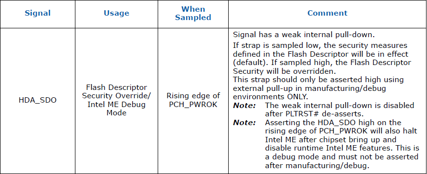
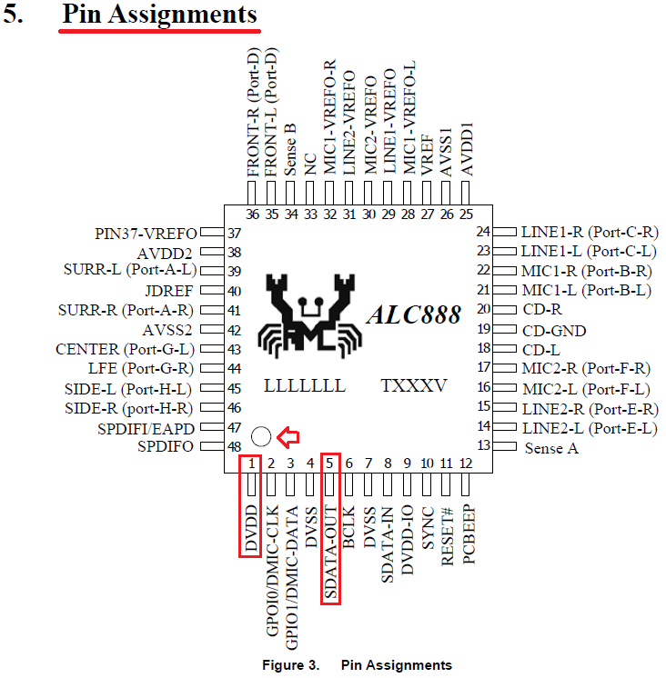
The official Intel method to unlock the Flash Descriptor on the field is commonly called "pinmod" and requires asserting HDA_SDO HIGH (Voltage/3.3V) during the rising edge of PWROK. To do that, you need to find your audio chip (HDA) at the motherboard and short two pins while the system starts.
To short the two pins, you need to use a small electrical conductor such as jumper, wire, paperclip, tweezers or similar. The pins are SDATA_OUT (or SDO) and DVDD (3.3V). For Realtek audio chips, which are the most common, these two pins are usually 1 & 5, starting from the dot/mark and moving counter clock-wise.
To perform the HDA_SDO/"pinmod" method, you need to follow these steps:
- Shutdown the system completely (S5 power state)
- Locate the two HDA pins and start shorting them
- Keep shorting the pins and power on the system
- Once the BIOS/OS starts to load, stop shorting
- The Flash Descriptor should now be unlocked
Note 1: The HDA_SDO/"pinmod" method is temporary and valid only until the next system reboot. You will otherwise need to perform it again.
Note 2: You should always verify the location of the SDATA_OUT and DVDD pins on your own audio chip, especially if it is not from Realtek, by finding the manufacturers’ datasheet and searching for the chips’ pinout diagram. Since finding Realtek datasheets is not always easy/possible, you can try the HDA_SDO/"pinmod" using the 1 & 5 rule of thumb. For other manufacturers (VIA, IDT etc), it is highly unlikely that pins 1 & 5 will work so try to find a datasheet. Usually, even datasheets from similar audio chip models will do just fine.
Note 3: During the HDA_SDO/"pinmod" state, depending on OEM/ODM configuration, some side-effects may be seen such as fan speed at 100%, no audio output, no Intel(R) Management Engine or Intel(R) Trusted Execution Engine driver at Device Manager and so on. These are all normal and will be restored to default after the HDA_SDO/"pinmod" state is over.
Note 4: Older platforms before 2011 (<= 5-series), did not use the HDA_SDO pin but required instead to assert GPIO33 LOW (Ground/GND) during the rising edge of PWROK. To do that, you need to find your motherboards’ GPIO33 pin location by looking at its OEM/ODM manual or service schematics and short two pins while the system starts, GPIO33 & GND.
Note 5: All modern audio chip/general purpose IO pins are usually very small so shorting two of them requires precision, steadiness and thus the use of thin/small electrical conductors. You may not succeed right away so keep trying. Always be extremely careful when shorting the pins because you may end up "frying" the audio chip of your motherboard otherwise.
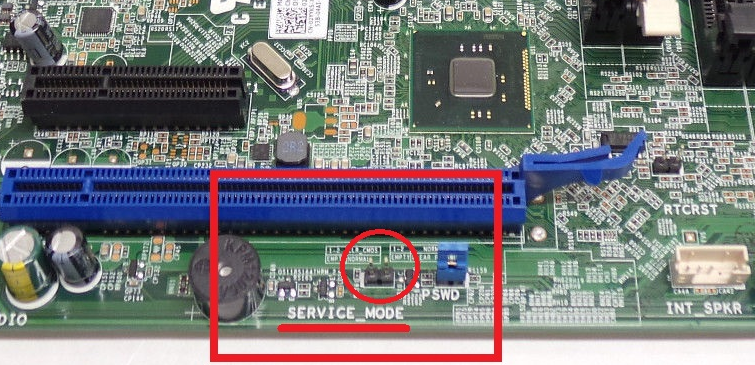
E2. Motherboard Jumper/Switch
Some motherboard vendors implement certain jumpers or switches which unlock the Flash Descriptor for system maintenance/servicing purposes. Depending on the OEMs’/ODMs’ implementation, these may unlock the entire SPI chip (FD + Engine + BIOS) or just the BIOS region for read/write access. You need to consult your motherboards’ manual or, in absence of that, the motherboard itself and find anything related to "Service Mode", "ME/TXE/SPS Unlock", "FD Unlock", "FD Override", "ME/TXE/SPS Service", "Manufacturing Mode" or similar. You need to set the jumper/switch while the system is shut down and at the next power on, the FD and/or BIOS regions should be unlocked.
Note 1: Unlike HDA_SDO/"pinmod", this method will work as long as the jumper/switch is set to enable read/write access to the FD. Remember to set it back once the system is repaired.
Note 2: During the enabled jumper/switch state, depending on OEM/ODM configuration, some side-effects may be seen such as fan speed at 100%, no audio output, no Intel(R) Management Engine or Intel(R) Trusted Execution Engine driver at Device Manager and so on. These are all normal and will be restored to default after the jumper/switch is set back to its default setting.
E3. OEM/ODM Servicing Features
Most system and/or motherboard vendors implement certain technologies which are meant to update or re-flash the systems’ firmware, either to improve or service it. Depending on the OEMs’/ODMs’ implementation, these may be able to automatically unlock the FD temporarily in order to initiate an update before locking it back again when they’re done (MSI M-Flash). They may be able to use a secondary/failsafe SPI chip which copies its contents to the primary/main one in case corruption is discovered on the latter (Gigabyte Dual BIOS). Other implementations however may only deal with specific regions of the SPI chip, mainly the BIOS, so they don’t unlock and are thus unable to repair the FD and/or Engine regions (ASUS BIOS Flashback, Samsung). Since there are many OEMs/ODMs and each one has their own system firmware recovery methods and requirements, depending on platform generation as well, you need to consult your systems’ or motherboards’ manual.
Note: A lot of "weak" OEM/ODM implementations are forced to respect the Flash Descriptor locks so they may not actually re-flash the usually locked FD or Engine regions despite appearances. Other "stronger" OEM/ODM implementations tend to use hidden BIOS options or Embedded Controller (EC) commands to temporarily unlock the FD for one boot, update/re-flash the firmware and then boot back up to a secure state in which SPI read/write access is blocked.
E4. OEM/ODM Servicing Utilities
Some system and/or motherboard vendors use certain factory floor servicing tools which are capable of unlocking or altering various aspects of a system. These are commonly used both during initial manufacturing and customer-requested repairing. In some cases, either by accident or intentionally (required for the provided update), these OEMs/ODMs leave those tools within their official end-user SPI/BIOS updates. You can thus use them to potentially unlock the Flash Descriptor locks and repair/update your Engine firmware or any other FD locked regions which might require servicing, such as the FD itself or GbE. So pay attention to the included files in your OEMs’/ODMs’ SPI/BIOS official update package for anything that might be capable of unlocking restricted access to the FD, Engine (ME/TXE/SPS), BIOS or similar. Some assumed logical tool names to look for are "ME/TXE/SPS Disable", "ME/TXE/SPS Unlock", "ME Set", "ME ON OFF", "DIS ME/TXE/SPS", "Boot Mode", "BIOS Unlock", "ME/TXE/SPS Jumper", "ME/TXE/SPS Override" and so on.
Note: Be careful when using such OEM/ODM servicing tools because they might not work with all models of a certain manufacturer’s product line/generation, even if the models are similar. This is especially important when said tools modify certain values at the EC firmware in order to unlock the FD. It is always recommended to use the tools provided with your own system’s SPI/BIOS update, if they are available of course.
E5. OEM/ODM BIOS-UEFI Options
Some motherboard vendors allow certain BIOS options to be changed which unlock the Flash Descriptor for system maintenance/servicing purposes. Depending on the OEMs’/ODMs’ implementation, these may unlock, for read/write access, the Engine region of the SPI chip only or all regions (FD + Engine + BIOS). Generally, the former is much more common that the latter. You need to consult your motherboards’ manual or, in absence of that, the BIOS itself and find anything related to "Me FW Image Re-Flash", "ME/TXE Disable", "HMRFPO", "Disable SPI/BIOS Protection" or similar. You need to set the option and after a restart to apply settings, the FD and/or Engine regions should be unlocked.
Note 1: Most manufacturers hide these options for security purposes but they can sometimes be shown either by hitting a special hotkey within the BIOS to enable a secret servicing menu (Acer), by powering on the system with certain keys/buttons pressed (HP) etc. Since this is highly OEM/ODM dependent, manual research on your manufacturer and/or model is required. So look around the web to find clues or try other methods.
Note 2: If a BIOS option enables read/write access to the Engine region of the SPI chip only, then you can repair its firmware but you cannot re-flash the FD or anything else that is not covered by the settings’ effect.
Note 3: Unlike HDA_SDO/"pinmod", this method will work as long as the BIOS option is set to enable read/write access to the FD and/or Engine region. Remember to set it back once the system is repaired.
Note 4: While the BIOS option is set, depending on OEM/ODM configuration, some side-effects may be seen such as fan speed at 100%, no audio output, no Intel(R) Management Engine or Intel(R) Trusted Execution Engine driver at Device Manager and so on. These are all normal and will be restored to default after the BIOS option is set back to its default value.
E6. OEM/ODM Hidden BIOS-UEFI Options
As mentioned above, various OEMs/ODMs allow certain BIOS options to be changed in order to unlock the SPI chip or at least the Engine region. However, for security purposes, most of them prefer to hide these options instead. On some cases, it may be possible to trigger these options by manually modifying the NVRAM/settings of the BIOS. The most basic requirement to try this method is for your BIOS/UEFI to support booting into an EFI environment to use its shell (command prompt). Usually, systems from 2012+ should be capable of booting into an EFI shell. Then, you need to download the latest UEFITool, IFR Extractor LS and attached "Setup EFI Shell". The goal is to find where a desired hidden BIOS option is located at the NVRAM/settings area of the BIOS and manually trigger it. To do that, you need to follow these steps:
- Download the same version SPI/BIOS image from your manufacturer or dump your own.
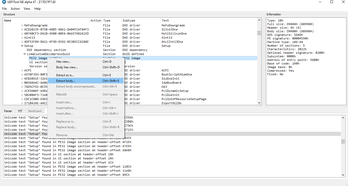
- Open the downloaded/dumped SPI/BIOS image in UEFITool and search for "Setup" string with Unicode option selected.
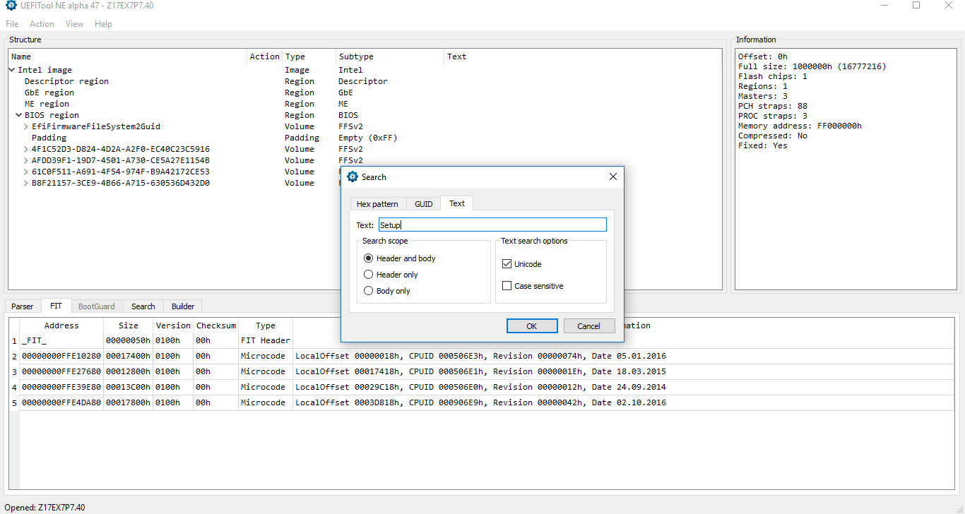
- At the results window, select one-by-one only those that are located in "UI" (User Interface) sections until you find the DXE driver named "Setup".
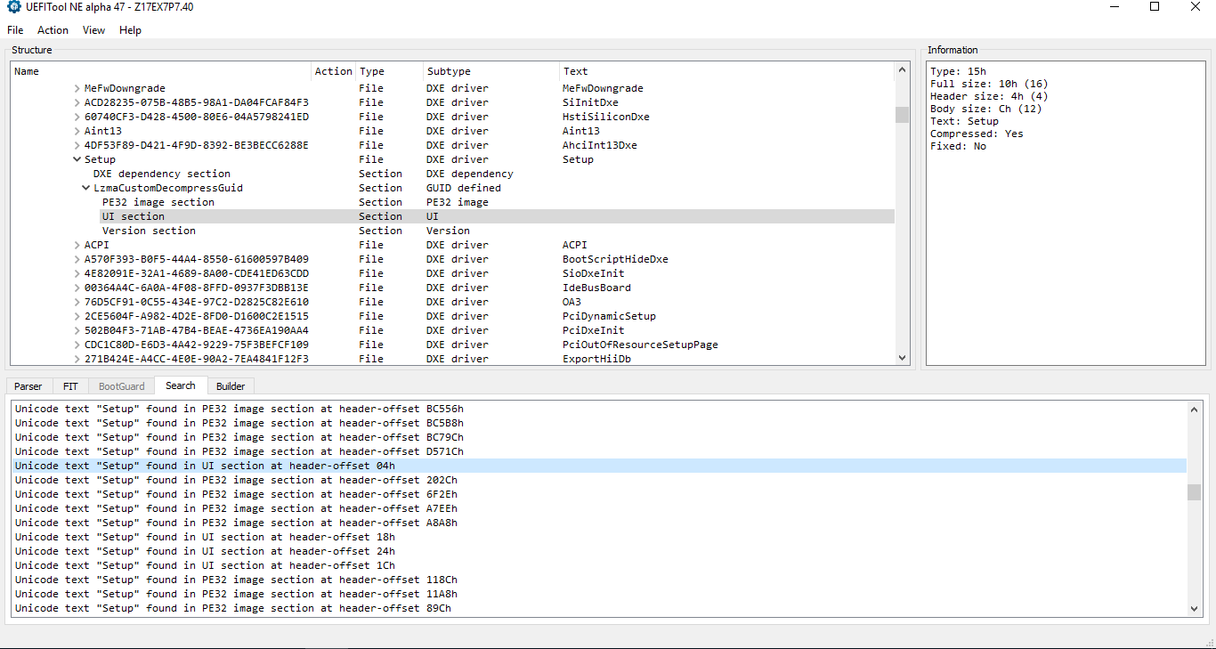
- Now you need to right click and "Extract [the] body" of the Setup DXE driver. Usually you need to extract the body of the "PE32 image section" but sometimes you may need the body of the entire "Setup" DXE driver or some sort of "Freeform subtype GUID" instead. Every BIOS can be different so you may need to experiment on your own.
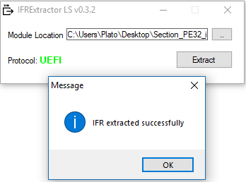
- Open the extracted file in IFR Extractor LS and you should see the Protocol change to "UEFI" in green letters. If it remains at "Unknown" in red letters, you may need to extract a different body or you may have found a wrong "Setup" DXE driver. Then Extract the IFR and save it as a text file.
- Open the text file and look for any BIOS option which might be interesting such as "Me FW Image Re-Flash", "ME Disable", "HMRFPO", "Lock" etc.
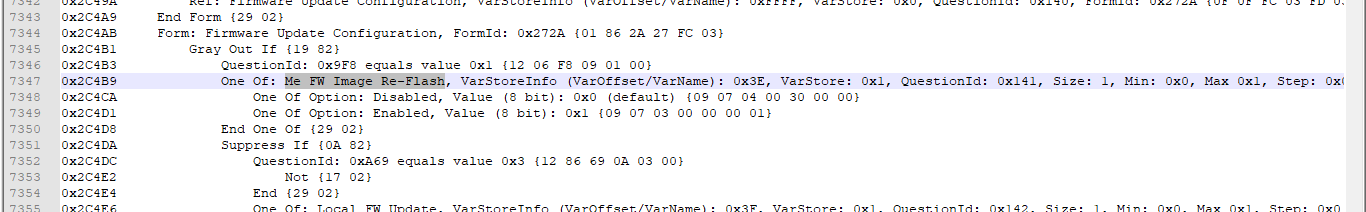
- Once you locate it, note down its "VarOffset" next to "VarStoreInfo" field which should be a hexadecimal number such as 0x3E, 0x6A7 and so on. You’ll also probably be able to see that the option is set by "default" to a non-desirable state. In this case, "Me FW Image Re-Flash" is set to "Disabled" by default but we want to "Enable" it temporarily. Note down the Enabled/Disabled "Value" of that BIOS option as well, usually 0x1 and 0x0 respectively.
- Copy the content of the EFI Shell archive, a single "efi" folder, to the root of a USB drive and boot from it when the system starts. You should reach an EFI Shell prompt.
- At the EFI Shell, run "setup_var 0x*** 0x^^" command, where *** = BIOS option "VarOffset" and ^^ = desired Enabled/Disabled "Value". In this example, we run "setup_var 0x3E 0x01". It should compete successfully.
- You now need to manually/forcefully reboot (Ctrl+Alt+Del) or reset the system and depending on the BIOS options’ effect, you should now have FD and/or Engine region read/write access.
Note 1: This method is highly dependent on a lot of factors and is thus not recommended unless you can recover from NVRAM corruption via a programmer or OEM/ODM emergency BIOS recovery implementations. Some of those factors are listed below, in no particular order. The hidden BIOS option may not actually work because the OEM/ODM never intended it to do so or never tested it. The OEM/ODM may have locked the NVRAM/settings so that they cannot be modified manually, for security purposes. After manually/forcefully restarting/resetting the system, it is possible for the BIOS to be set in such a way as to automatically re-assign any hidden (none user accessible) options to default, thus restoring the value you just tried to change. The altered setup variable may not necessarily correspond to what you saw at the IFR text file which may cause unexpected behavior in case something else ends up being modified by accident. The BIOS may refuse to boot if an unsanctioned NVRAM modification is detected, thus leaving the user with a soft-brick.
Note 2: The same method can be followed in order to disable some OEM/ODM BIOS Locks or Protected Range Registers by looking for "BIOS Lock" or similar hidden BIOS options at the extracted IFR text file from the "Setup" DXE driver. Since the BIOS region is not locked by the Flash Descriptor and thus not relevant to it, any BIOS lock related questions are out of scope for this thread. Instead, you can ask for help at BIOS related sub-forums or threads.
E7. Hardware SPI Programmer
The easiest, fastest and safest (when something goes wrong) method to bypass the Flash Descriptor read/write access locks is to use a hardware programmer to reprogram the entire SPI chip. This method requires more advanced users who own and know how to use a programmer. This can be done either by removing a socketed/removable SPI chip (not common) or directly on the motherboard (may not always work) or by de-soldering, programming and then re-soldering the chip back. If you want to buy a hardware programmer, you can get the job done even with ones which cost around 5$ (CH341A, Raspberry Pi etc).
Note 1: Since the FD locks are implemented in software, they cannot block hardware programmer re-flashing but only software-based general purpose SPI flashers such as AMI AFU, Intel Flash Programming Tool, Flashrom etc.
Note 2: If the SPI chip is socketed or you have re-soldering tools & knowledge, the programmer by itself is enough. If you plan to try SPI chip re-flashing while it is still soldered to the motherboard, you’ll also need a clip and maybe a more expensive programmer with enough output current to power the entire motherboard and thus read/write the contents of the chip.
Note 3: Programmer, soldering or wiring related questions are out of scope for this thread. Instead, you can ask for help at programmer related threads such as this or this.
Setup_EFI_Shell.rar (651 KB)


