Clean Dumped Intel Engine (CS)ME/(CS)TXE
Regions with Data Initialization
Last Updated: 2020-07-22
This guide is relevant to those who need to clean the DATA section of an Engine (CSME, ME, CSTXE, TXE) Region, which is part of a dumped SPI/BIOS image, in order to flash the latter on a different machine of the same OEM model. It is not meant as a guide on how to completely transform a dumped Engine region into a stock Intel-provided one. Although the guide can be used for that sometimes, the goal is not to update the firmware but to clean the already existing one inside the dumped SPI/BIOS image from any system-specific data while maintaining any configuration settings applied by the OEM of the given model. In this guide, the term "system" means an individual user machine whereas "model" refers to all those "systems" released by the OEM.
A. About Engine Regions & Configuration
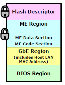
The SPI/BIOS chip firmware is divided into regions which control different aspects of an Intel-based system. The mandatory regions are the Flash Descriptor (FD, controls read/write access between the regions among other things), the (Converged Security) Management or Trusted Execution Engine (CSME/CSTXE/ME/TXE, holds the Engine firmware which has been configured for a specific system) and the BIOS. The Type of each (CS)ME/(CS)TXE firmware Region can be either Stock (RGN, clean/stock/unconfigured images provided by Intel to OEMs) or Extracted (EXTR, dirty/extracted/configured images from various SPI/BIOS). The (CS)ME or (CS)TXE firmware at the system's SPI/BIOS chip is always EXTR, generated by the OEM after configuring the equivalent RGN at the factory via Intel Flash Image Tool (FIT).
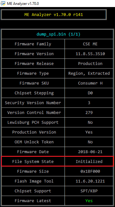
The Engine firmware Regions (RGN/EXTR) consist of two sections: CODE and DATA. CODE is the actual Engine firmware whereas DATA is where all the system-specific settings are stored, as configured by the OEM at the factory via Intel Flash Image Tool. The Engine firmware is not static as it holds system-specific configuration and can additionally be slightly configured by the Engine co-processor while the system is running in order to provide the proper support and functionality. Any such changes are written into the DATA section of the Engine Region and the firmware is considered initialized. That means that the DATA section can be in one of three states: Unconfigured, Configured or Initialized. Unconfigured means that the Engine firmware image is the stock one Intel provides and not configured at all (RGN). Configured means that the OEM has applied model specific settings and the Engine region is ready for deployment (EXTR). Initialized means that the Engine region comes from a system which was already running and thus the Engine co-processor has further configured the DATA section to suit that particular system better (system specific or dirty EXTR).
A dumped SPI/BIOS image comes from a system which was already operating so the contained Engine Region should have a Initialized DATA section. In order for that dump to be usable on another system of the same OEM model we need to clean the "Initialization" extra data and thus end up with an Engine Region which has a Configured-only DATA section. This is important because on some cases these small dumped "initialization" changes made by the Engine co-processor of a system can lead to a malfunctioning or a corrupted Engine Region when transferred to another system even one of the same OEM model.
B. Helpful Resources
First you need to identify what Engine firmware the dumped SPI/BIOS image has inside. For that you can use ME Analyzer tool which is capable of telling you the version, sku, release, type etc of any inputted Engine firmware. You can use it to analyze both the dumped SPI/BIOS image you plan to clean and the firmware with which you plan to achieve that. The latter can be retrieved from Intel (CS)ME, CS(TXE), CS(SPS), PMC, PHY & PCHC Firmware Repositories thread which includes all Engine (CSME, ME, CSTXE, TXE) firmware that we have gathered for such cases.
Before proceeding, make sure to also check the dedicated Intel Management Engine: Drivers, Firmware & System Tools and Intel Trusted Execution Engine: Drivers, Firmware & System Tools threads first. There you can find some more information about each firmware's chipset compatibility as well as the Engine System Tools packages which include the Flash Image Tool (FIT/FITC/FTOOLC) which we will be using for the cleanup process. You will also understand various terms which are used throughout the guide such as FIT, FITC, FTOOLC, CSE, CSME, CSTXE, RGN, EXTR, UPD, FD and so on.
C. Method Compatibility
This method has been tested to work on (CS)ME 2 - 15 and (CS)TXE 1 - 4. The process depending on the generation, so the guide differs. It has not been tested on any (CS)SPS firmware.
Since the purpose of the guide is to clean the DATA section, it is important to choose a clean RGN Engine firmware from the Intel Engine Firmware Repositories thread and not EXTR which is extracted from various SPI/BIOS images/dumps and considered dirty as far as the DATA section is concerned. Moreover, a full RGN Engine Region is required and not an Update (UPD) image. That means that you should look only for Engine firmware of this structure at the Repositories:
Major.Minor.Hotfix.Build_SKU_PRD_RGN
As previously mentioned, the goal is not necessarily to update the Engine firmware so you can choose any RGN firmware of the same SKU as long as the major and minor versions are the same. It is usually recommended to take the exact same RGN firmware from the repositories, otherwise the closest you can find in case that one doesn't exist or it's not RGN, same SKU etc.
D. Clean the Initialized DATA section
D0. Index
D1. ME 2 - 3
D2. ME 4 - 6
D3. ME 7 - 10 & TXE 1 - 2
D4. CSME 11 - 15 & CSTXE 3 - 4
D1. ME 2 - 3
In this section we have taken as an example a SPI/BIOS image dump of a model which comes with ME firmware version 9.1.x.xxxx and SKU 1.5MB. However, the same applies to ME 2 - 3 firmware.
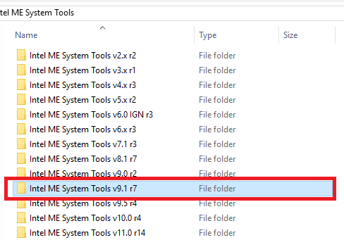
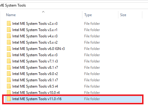
1. From Intel Management Engine: Drivers, Firmware & System Tools thread, make sure you have downloaded the correct System Tools package and extract it.
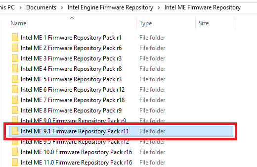
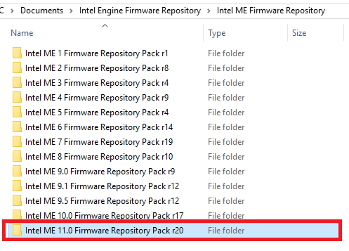
2. From Intel (CS)ME, CS(TXE), CS(SPS), PMC, PHY & PCHC Firmware Repositories thread, make sure you have downloaded the correct Repository pack based on major/minor version and extract it.
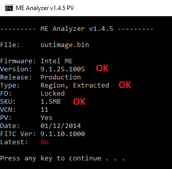
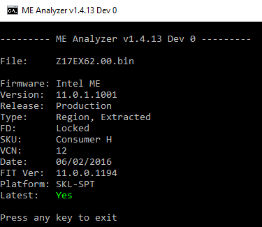
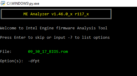
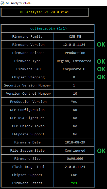
3. Open the dumped SPI/BIOS image with ME Analyzer to see what major/minor version we need as well as SKU. In this case we have:
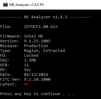
So our SPI/BIOS image dump has a ME 9.1 firmware with 1.5MB SKU.
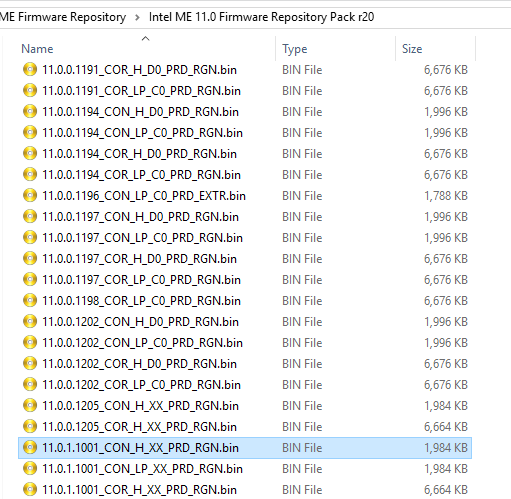
4. Browse the Repository pack, copy the same (or as similar as possible) ME RGN firmware of the same SKU and major/minor version (as instructed above) somewhere and then rename it to "ME Region.bin". In this case:
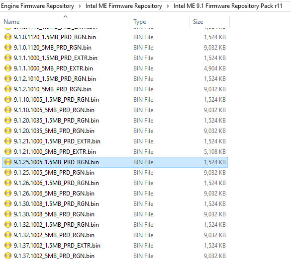
So we pick the firmware file 9.1.25.1005_1.5MB_PRD_RGN which matches perfectly what we saw at ME Analyzer. If for example the dumped SPI/BIOS image had ME 9.1.37.1002, we would have picked ME 9.1.32.1002 instead because the one we wanted is EXTR and not RGN. Thus, we rename the "9.1.25.1005_1.5MB_PRD_RGN.bin" copy to "ME Region.bin".
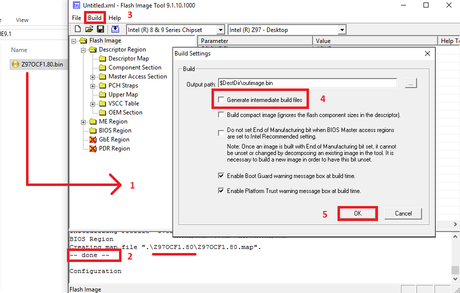
5. From the System Tools folder, go to Flash Image Tool subfolder and run ftoolc.exe. Drag & drop the dumped SPI/BIOS image you want to clean. After it is done loading:
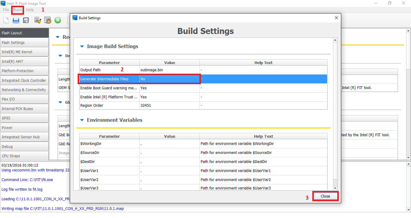
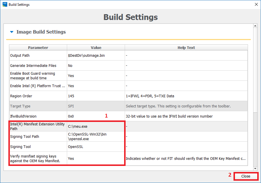
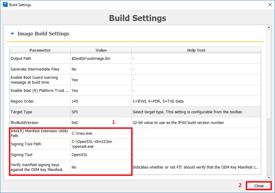
- Go to Build > Build Settings... , untick the option to "Generate intermediate build files", leave all other settings intact and click OK.
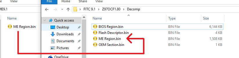
6. Keep the FTOOLC window open. At the FITC folder there should now be a folder named after the inputted file, in this case it's named "Z97OCF1.80". Enter "Decomp" subfolder. There should be a number of files there (BIOS Region, Flash Descriptor, OEM Region etc) including a "ME Region.bin" file. Take the previous "ME Region.bin" file you saved at step 4 and copy it where the current "ME Region.bin" file is, effectively replacing it.
7. Go to the already open FTOOLC window, click the "Build Image" icon (or "Build > Build Image"), save as "intermediate.bin" and it should complete successfully.
8. At the FTOOLC folder you should now see a file named "intermediate.bin" which is the dumped SPI/BIOS image with an Engine region which has an "Unconfigured" DATA section without any needed "Configuration" or unneeded "Initialization" information stored. Thus, it now needs to be "Configured".
9. From the System Tools folder, go to iAMTNVM subfolder and open a command prompt there. Copy the original input image (for example: "input.bin") as well as the Unconfigured one ("intermediate.bin") at the iAMTNVM subfolder. At the command prompt, enter "AMTNVM.exe -parse input.bin -out config.txt". A "config.txt" file should be created which holds the input firmware configuration. To transfer it into the Unconfigured image, enter "AMTNVM.exe -edit intermediate.bin config.txt -out outimage.bin" which should build the final "Configured" output SPI/BIOS image.
10. Now, you need to verify that the resulting image has the same configured DATA settings as the imported one.
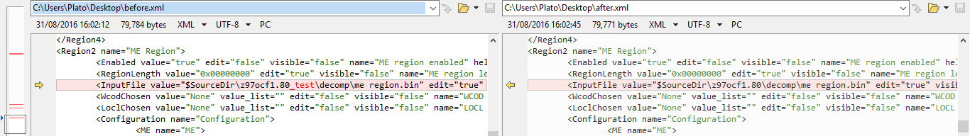
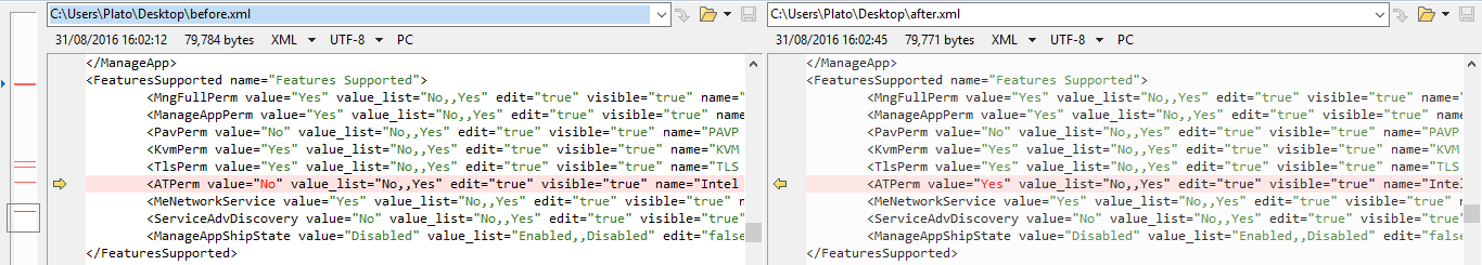
- Remove any leftover temporary files from FTOOLC's directory (folders, ftool.ini, ftool.log). Run FTOOLC and drag & drop the output file. Go to "File > Save As" and save the configuration xml file with a descriptive name such as "after.xml". Afterwards, close the FTOOLC window. Repeat this step for the original image and you should end up with two configuration xml files, in this case they are named "before.xml" and "after.xml". Open these two files in any comparison tool that supports XML and check for any differences. All settings should be identical apart from "InputFile" fields.
- Go to iAMTNVM subfolder and open a command prompt there. At the command prompt, enter "AMTNVM.exe -parse input.bin -out before.txt" followed by "AMTNVM.exe -parse outimage.bin -out after.txt". You should end up with two configuration txt files, in this case they are named "before.txt" and "after.txt". Open these two files in any comparison tool and check for any differences. All settings should be identical.
- Import the output file to ME Analyzer and check if the Major/Minor versions & SKU are the same as before. Also, make sure the Type is reported as "Extracted" which means that the inputted image is OEM/FTOOLC configured. Whether the DATA section is now Configured and not Initialized cannot be checked/verified by ME Analyzer but if you followed the above steps properly you should not be having any issues.
D2. ME 4 - 6
In this section we have taken as an example a SPI/BIOS image dump of a model which comes with ME firmware version 9.1.x.xxxx and SKU 1.5MB. However, the same applies to ME 4 - 6 firmware.
1. From Intel Management Engine: Drivers, Firmware & System Tools thread, make sure you have downloaded the correct System Tools package and extract it.
2. From Intel (CS)ME, CS(TXE), CS(SPS), PMC, PHY & PCHC Firmware Repositories thread, make sure you have downloaded the correct Repository pack based on major/minor version and extract it.
3. Open the dumped SPI/BIOS image with ME Analyzer to see what major/minor version we need as well as SKU. In this case we have:
So our SPI/BIOS image dump has a ME 9.1 firmware with 1.5MB SKU.
4. Browse the Repository pack, copy the same (or as similar as possible) ME RGN firmware of the same SKU and major/minor version (as instructed above) somewhere and then rename it to "ME Region.bin". In this case:
So we pick the firmware file 9.1.25.1005_1.5MB_PRD_RGN which matches perfectly what we saw at ME Analyzer. If for example the dumped SPI/BIOS image had ME 9.1.37.1002, we would have picked ME 9.1.32.1002 instead because the one we wanted is EXTR and not RGN. Thus, we rename the "9.1.25.1005_1.5MB_PRD_RGN.bin" copy to "ME Region.bin".
5. From the System Tools folder, go to Flash Image Tool subfolder and run fitc.exe. Drag & drop the dumped SPI/BIOS image you want to clean. After it is done loading:
- Go to Build > Build Settings... , untick the option to "Generate intermediate build files", leave all other settings intact and click OK.
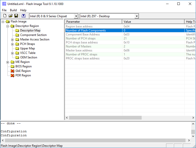
- If you are working on an Engine region only (extracted via Flash Programming Tool with "-me" parameter or via UEFITool > ME region > Extract as is...) and not a full SPI/BIOS image (Flash Descriptor + Engine + BIOS), go to "Flash Image > Descriptor Region > Descriptor Map" and set "Number of Flash Components" to "0".
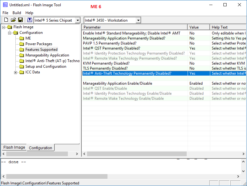
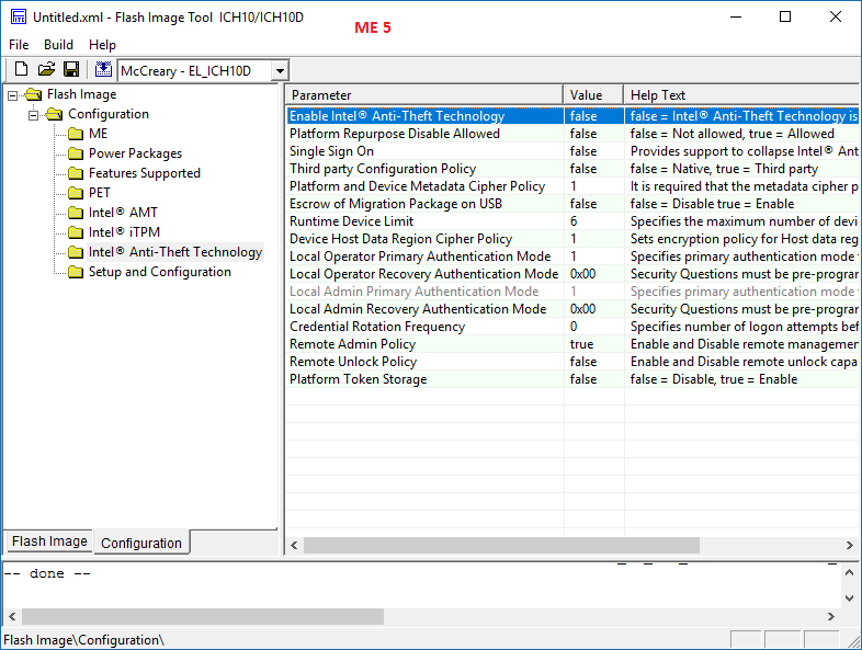
- If you are working on ME 5 - 6, go to Flash Image > Configuration > "Features Supported" or "Intel Anti-Theft Technology" and set "Intel (R) Anti-Theft Technology Permanently Disabled?" to "Yes" or "Enable Intel Anti-Theft Technology" to "false". Intel Anti-Theft Technology has been EOL since January 2015 and can cause issues if left activated nowadays.
6. Keep the FITC window open. At the FITC folder there should now be a folder named after the inputted file, in this case it's named "Z97OCF1.80". Enter "Decomp" subfolder. There should be a number of files there (BIOS Region, Flash Descriptor, OEM Region etc) including a "ME Region.bin" file. Take the previous "ME Region.bin" file you saved at step 4 and copy it where the current "ME Region.bin" file is, effectively replacing it.
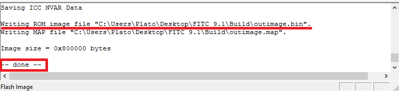
7. Go to the already open FITC window, click the "Build Image" icon (or "Build > Build Image") and it should complete successfully.
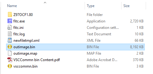
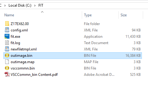
8. At the FITC folder you should now see a file named "outimage.bin" which is the dumped full SPI/BIOS (or ME) image with an Engine region which has a Configured DATA section without any unneeded "Initialization" information stored.
9. Now, you need to verify that the resulting image has the same configured DATA settings as the imported one.
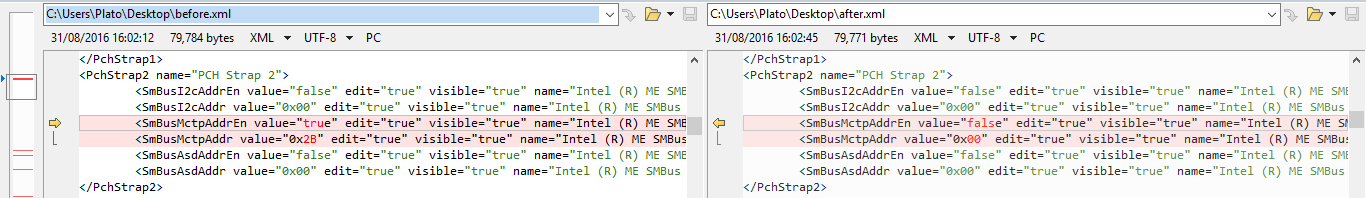
- Remove any leftover temporary files from FITC's directory (folders, fitc.ini, fitc.log). Run FITC and drag & drop the output file. Go to "File > Save As" and save the configuration xml file with a descriptive name such as "after.xml". Afterwards, close the FITC window. Repeat this step for the original image and you should end up with two configuration xml files, in this case they are named "before.xml" and "after.xml". Open these two files in any comparison tool that supports XML and check for any differences. All settings should be identical apart from "InputFile" fields and possibly Intel Anti-Theft related ones such as "SmBusMctpAddrEn", "SmBusMctpAddr" & "ATPerm", if those required changes at step 5.
- If you are working on ME 6, remove any leftover temporary files from FITC's directory (folders, fitc.ini, fitc.log, before.xml, after.xml etc). Run FITC and drag & drop the output file. Rename the file "ConfigParams.txt" to "before.txt" and close FITC. Run FITC and drag & drop the original file. Rename the file "ConfigParams.txt" to "after.txt" and close FITC. You should end up with two configuration txt files, in this case they are named "before.txt" and "after.txt". Open these two files in any comparison tool and check for any differences. All settings should be identical apart from any Intel Anti-Theft related ones, if those required changes at step 5.
- If you are working on ME 4 - 5, remove any leftover temporary files from FITC's directory (folders, fitc.ini, fitc.log, before.xml, after.xml etc). Run FITC, drag & drop the output file and close it. Run FITC, drag & drop the original file and close it. At the FITC folder there should now be two folders named after the inputted files. At each input file folder, enter "Decomp" subfolder, copy "Configuration.txt" (ME 5) or "NVARs.txt" (ME 4) file and rename them to "before.txt" and "after.txt" respectively. You should end up with two configuration txt files, in this case they are named "before.txt" and "after.txt". Open these two files in any comparison tool and check for any differences. All settings should be identical apart from any Intel Anti-Theft related ones, if those required changes at step 5.
- Import the output file to ME Analyzer and check if the Major/Minor versions & SKU are the same as before. Also, make sure the Type is reported as "Extracted" which means that the inputted image is OEM/FITC configured. Whether the DATA section is now Configured and not Initialized cannot be checked/verified by ME Analyzer but if you followed the above steps properly you should not be having any issues.
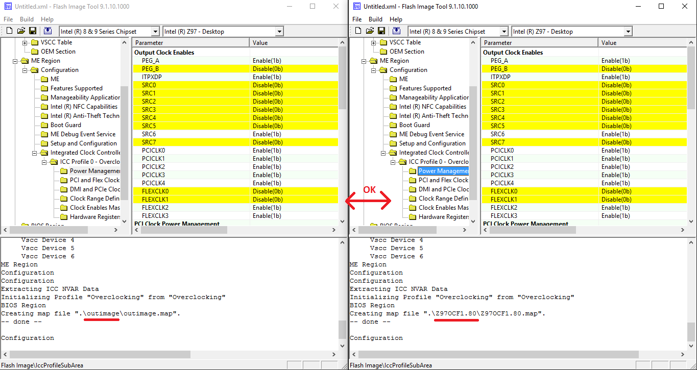
- As an extra verification step, you can open your original SPI/BIOS image dump in one FITC window and the output image in another and manually check quickly if the Engine Region settings are identical at both. This method is not needed if you have already checked via the configuration xml & txt files, it is not recommended because some settings are not visible at the FITC window but only at the configuration files and it requires a lot of time for manual comparisons.
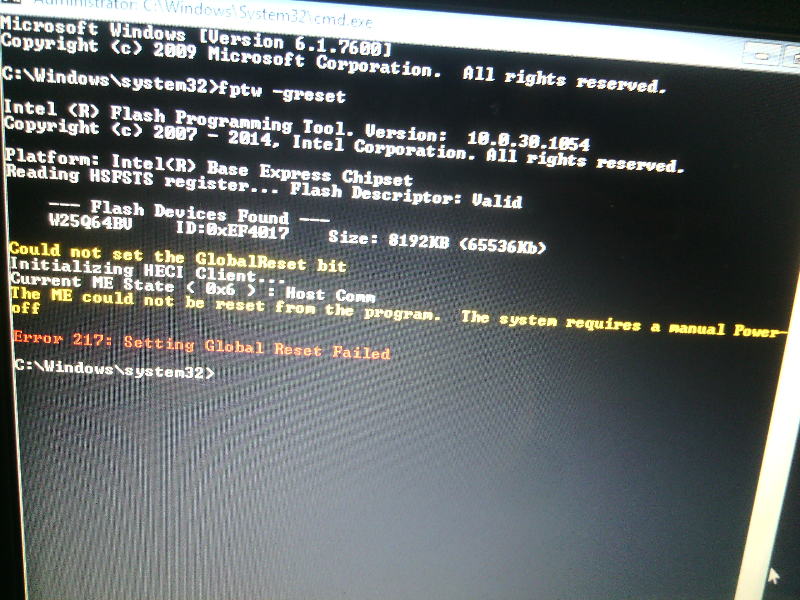
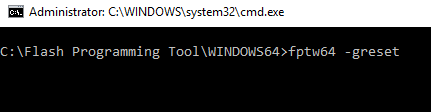
10. Last but not least, if you are working on ME 5 - 6, once your new cleaned+configured full SPI/BIOS dump or Engine region is flashed on the target system, run Flash Programming Tool with command fpt -greset and wait for the system to reset (no settings are lost). This step is very important because it forces the Engine co-processor to re-initialize and properly accept any changes to its SPI/BIOS image region counterpart.
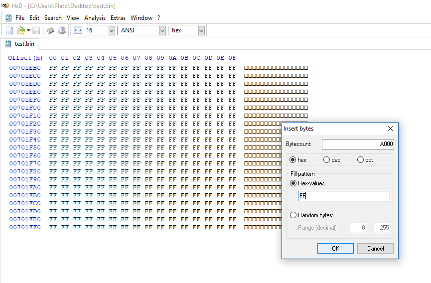
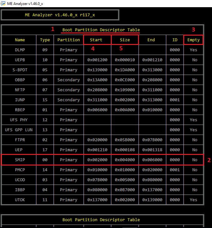
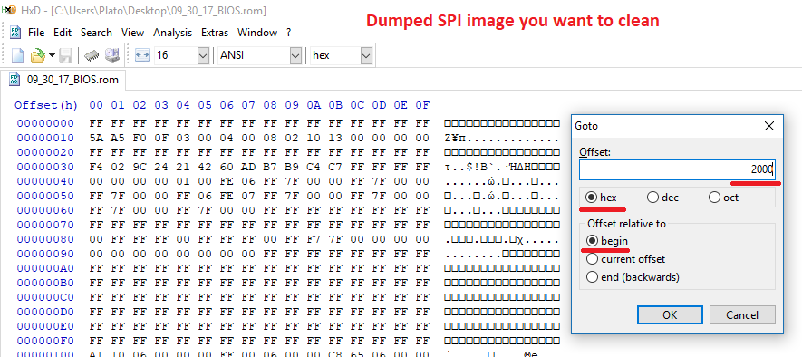
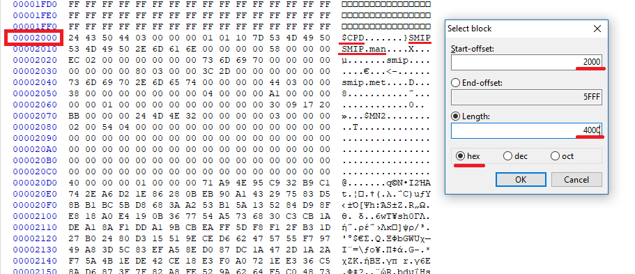
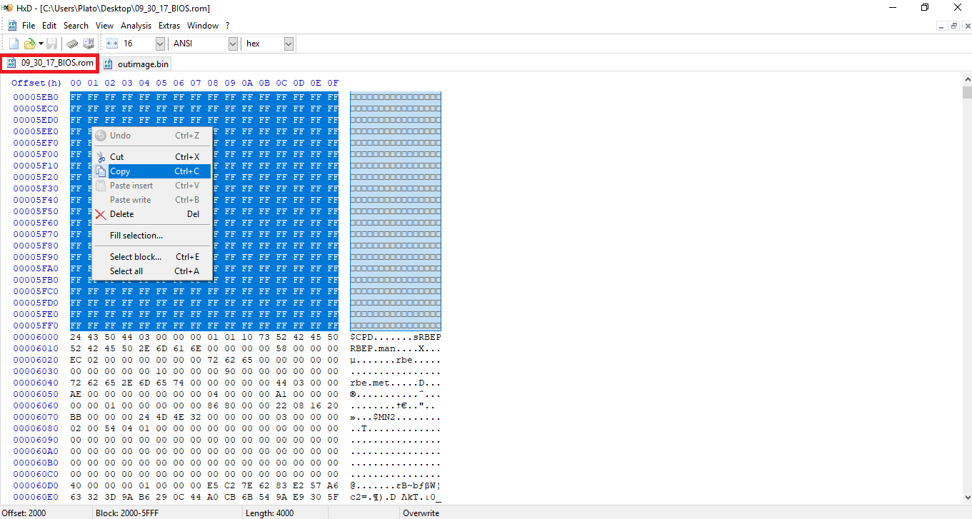
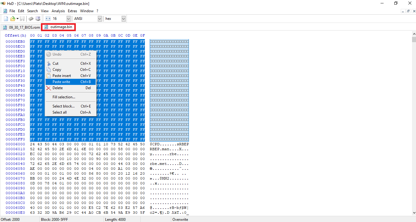
- If you are working on an Engine region only (extracted via Flash Programming Tool with "-me" parameter or via UEFITool > ME region > Extract as is...) and not a full SPI/BIOS image (Flash Descriptor + Engine + BIOS), make sure that the output region has the same size at the input/dumped one. To do that, subtract the output region size from the input/dumped one to get the difference, which is the amount of 0xFF padding that needs to be appended at the end of the output region using a hex editor. For example, in a hypothetical case in which the size difference is 0xA000, the output region would need to be adjusted in HxD Hex Editor like so:
D3. ME 7 - 10 & TXE 1 - 2
In this section we have taken as an example a SPI/BIOS image dump of a model which comes with ME firmware version 9.1.x.xxxx and SKU 1.5MB. However, the same applies to all ME 7 - 10 and TXE 1 - 2 firmware.
1. From Intel Management Engine: Drivers, Firmware & System Tools or Intel Trusted Execution Engine: Drivers, Firmware & System Tools threads, make sure you have downloaded the correct System Tools package and extract it.
2. From Intel (CS)ME, CS(TXE), CS(SPS), PMC, PHY & PCHC Firmware Repositories thread, make sure you have downloaded the correct Repository pack based on major/minor version and extract it.
3. Open the dumped SPI/BIOS image with ME Analyzer to see what major/minor version we need as well as SKU. In this case we have:
So our SPI/BIOS image dump has a ME 9.1 firmware with 1.5MB SKU.
4. Browse the Repository pack, copy the same (or as similar as possible) ME/TXE RGN firmware of the same SKU and major/minor version (as instructed above) somewhere and then rename it to "ME Region.bin" or "TXE Region.bin" depending on what you're working with. In this case:
So we pick the firmware file 9.1.25.1005_1.5MB_PRD_RGN which matches perfectly what we saw at ME Analyzer. If for example the dumped SPI/BIOS image had ME 9.1.37.1002, we would have picked ME 9.1.32.1002 instead because the one we wanted is EXTR and not RGN. Thus, we rename the "9.1.25.1005_1.5MB_PRD_RGN.bin" copy to "ME Region.bin".
5. From the System Tools folder, go to Flash Image Tool subfolder and run fitc.exe. Drag & drop the dumped SPI/BIOS image you want to clean. After it is done loading:
- Go to Build > Build Settings... , untick the option to "Generate intermediate build files", leave all other settings intact and click OK.
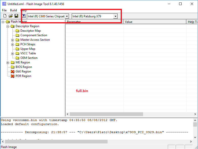
- If you are working on FITC v8.1.40.1456 with ME 8 firmware which is configured as any "Intel (R) C600 Series Chipset" (Patsburg SKU), then you must use a ME region only for the cleanup process and not a SPI/BIOS image. So if you have a SPI/BIOS image, first extract the ME region and then load it to FITC. That is due to a FITC bug in which Patsburg settings are not properly shown/transferred when using anything but a bare Engine region image (extracted via Flash Programming Tool with "-me" parameter or via UEFITool > ME region > Extract as is...). More info can be found here. When you load the bare ME region at FITC, if the SKU at the top bars does not match what you see when loading the full SPI/BIOS image, make sure to first adjust that accordingly and don't leave it empty or different.
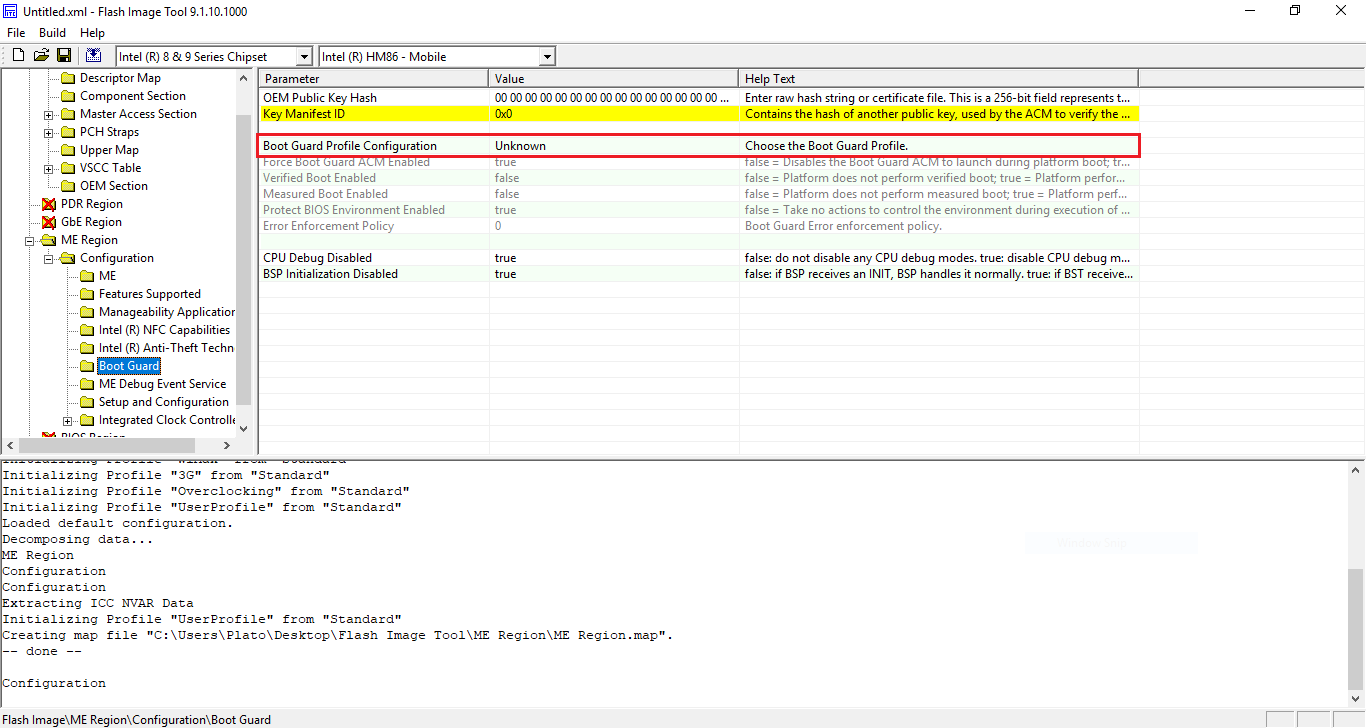
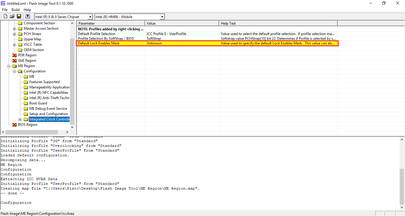
- If you are working on ME 9, go to "Flash Image > ME Region > Configuration > Boot Guard" and make sure that "Boot Guard Profile Configuration" is not set to "Unknown". If it is set to "Unknown", change it to the default value of "Boot Guard Profile 0 - No_FVME". Also, go to "Flash Image > ME Region > Configuration > Integrated Clock Controller" and make sure that "Default Lock Enables Mask" is not set to "Unknown". If it is set to "Unknown", change it to the default value of "0:Default".
- If you are working on an Engine region only (extracted via Flash Programming Tool with "-me" parameter or via UEFITool > ME region > Extract as is...) and not a full SPI/BIOS image (Flash Descriptor + Engine + BIOS), go to "Flash Image > Descriptor Region > Descriptor Map" and set "Number of Flash Components" to "0".
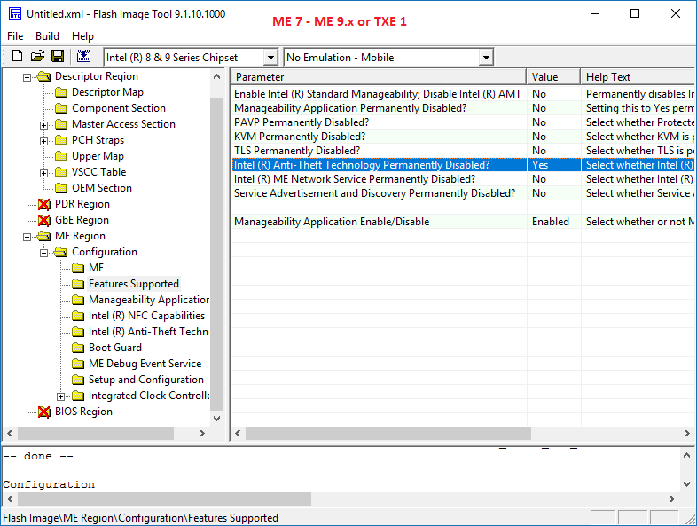
- If you are working on ME 7 - 9 or TXE 1, go to Flash Image > ME/TXE Region > Configuration > Features Supported and set "Intel (R) Anti-Theft Technology Permanently Disabled? " to "Yes". Intel Anti-Theft Technology has been EOL since January 2015 and can cause issues if left activated nowadays.
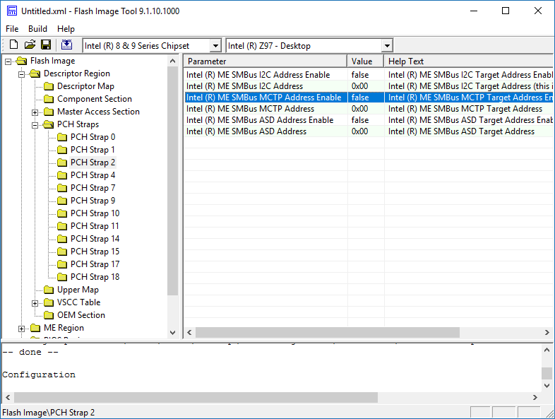
- If you are working on a SPI/BIOS image with ME 7 - 9, go to Flash Image > Descriptor Region > PCH Straps > PCH Strap 2 and set "Intel (R) ME SMBus MCTP Address Enable" to "false". Also, set "Intel (R) ME SMBus MCTP Address" to "0x00". These are Intel Anti-Theft Technology settings and these changes will stop the "MCTP 3G" error seen at Intel MEManuf tool when the former is disabled.
Note: These two settings are set at the Flash Descriptor (first 4KB of a full SPI/BIOS image) and not at the Engine Region (extracted via Flash Programming Tool with "-me" parameter or via UEFITool > ME region > Extract as is...). So for these to apply, you need to reflash the FD as well either by preparing a full SPI/BIOS image (Flash Descriptor + Engine + BIOS) or by flashing it manually via a tool such as Flash Programming Tool with -desc command.
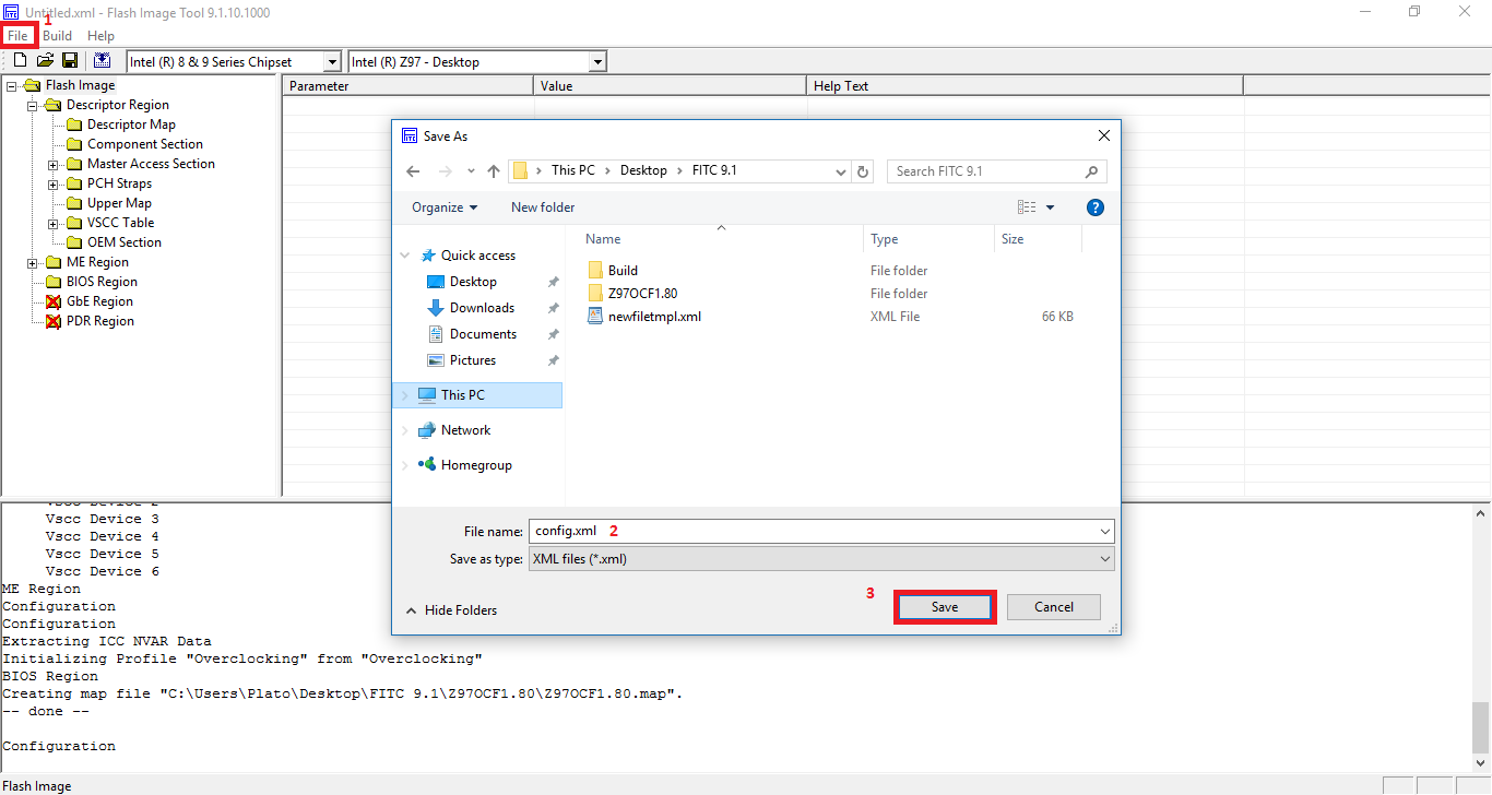
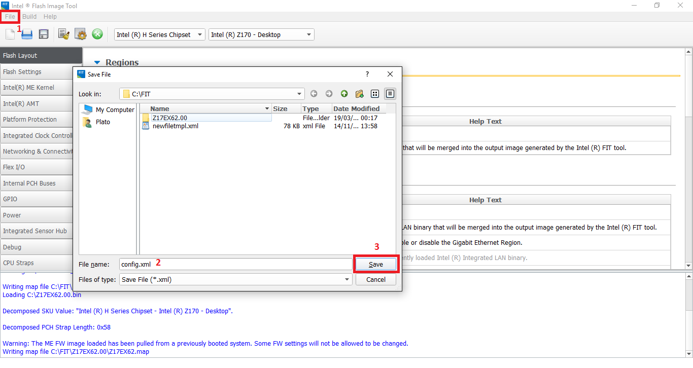
6. Go to "File > Save As" and save the configuration xml file, in this case it's named "config.xml". Afterwards, close the FITC window.
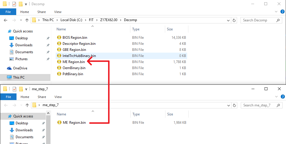
7. At the FITC folder there should now be a folder named after the inputted file, in this case it's named "Z97OCF1.80". Enter "Decomp" subfolder. There should be a number of files there (BIOS Region, Flash Descriptor, OEM Region etc) including a "ME Region.bin" or "TXE Region.bin" file. Take the previous "ME Region.bin" or "TXE Region.bin" file you saved at step 4 and copy it where the current "ME Region.bin" or "TXE Region.bin" file is, effectively replacing it.
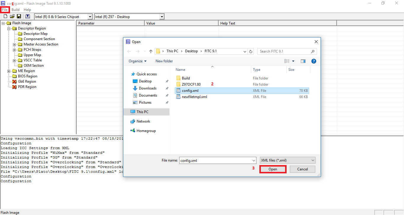
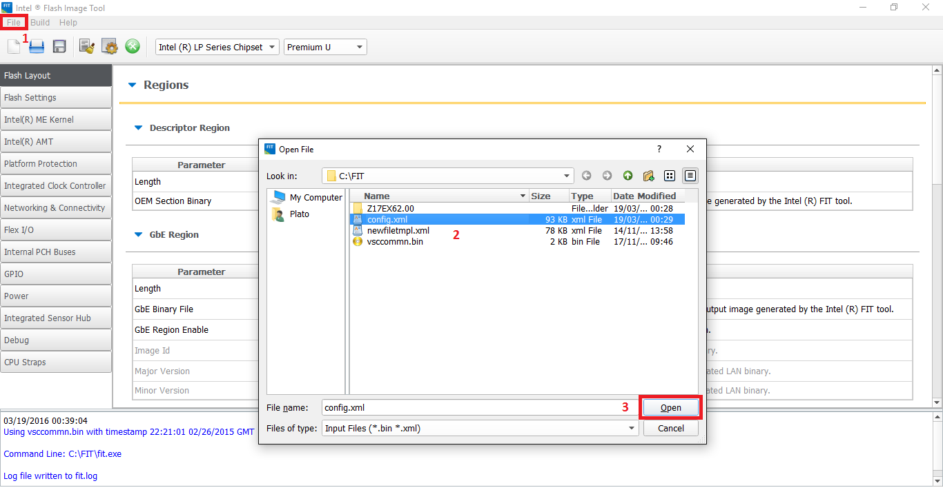
8. Run FITC again. From "File > Open" select the saved configuration xml file from step 6 and open it.
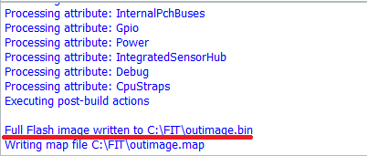
9. Click the "Build Image" icon (or "Build > Build Image") and it should complete successfully.
10. At the FITC folder you should now see a file named "outimage.bin" which is the dumped SPI/BIOS (or ME/TXE) image with an Engine region which has a Configured DATA section without any unneeded "Initialization" information stored.
11. Now, you need to verify that the resulting image has the same configured DATA settings as the imported one.
- Remove any leftover temporary files from FITC's directory (folders, fitc.ini, fitc.log). Run FITC and drag & drop the output file. Go to "File > Save As" and save the configuration xml file with a descriptive name such as "after.xml". Afterwards, close the FITC window. Repeat this step for the original image and you should end up with two configuration xml files, in this case they are named "before.xml" and "after.xml". Open these two files in any comparison tool that supports XML and check for any differences. All settings should be identical apart from "InputFile" fields and possibly Intel Anti-Theft related ones such as "SmBusMctpAddrEn", "SmBusMctpAddr" & "ATPerm", if those required changes at step 5.
- Import the output file to ME Analyzer and check if the Major/Minor versions & SKU are the same as before. Also, make sure the Type is reported as "Extracted" which means that the inputted image is OEM/FITC configured. Whether the DATA section is now Configured and not Initialized cannot be checked/verified by ME Analyzer but if you followed the above steps properly you should not be having any issues.
- As an extra verification step, you can open your original SPI/BIOS image dump in one FITC window and the output image in another and manually check quickly if the Engine Region settings are identical at both. This method is not needed if you have already checked via the configuration xml files, it is not recommended because some settings are not visible at the FITC window but only at the configuration file and it requires a lot of time for manual comparisons.
12. Last but not least, once your new cleaned+configured full SPI/BIOS dump or Engine region is flashed on the target system, run Flash Programming Tool with command fpt -greset and wait for the system to reset (no settings are lost). This step is very important because it forces the Engine co-processor to re-initialize and properly accept any changes to its SPI/BIOS image region counterpart.
- If you are working on an Engine region only (extracted via Flash Programming Tool with "-me" parameter or via UEFITool > ME region > Extract as is...) and not a full SPI/BIOS image (Flash Descriptor + Engine + BIOS), make sure that the output region has the same size at the input/dumped one. To do that, subtract the output region size from the input/dumped one to get the difference, which is the amount of 0xFF padding that needs to be appended at the end of the output region using a hex editor. For example, in a hypothetical case in which the size difference is 0xA000, the output region would need to be adjusted in HxD Hex Editor like so:
 . Thanks for all the work you guys are doing, it’s clear, works and takes a lot of effort!